
A complete 2D site plan design must include: property boundary lines derived from certified survey data; dimensioned setbacks from all structures to each boundary; the accurate footprint and orientation of all existing and proposed buildings; access points and internal circulation routes; drainage and stormwater management features; utility connections (water, sewer, gas, electrical); landscape elements; a north arrow; a metric bar scale; and a clear title block containing the project name, preparer’s credentials, and drawing date. These elements collectively satisfy the legal, zoning, and technical requirements of planning authorities across the UK, US, and most international jurisdictions – and a site plan missing any one of them risks invalidating the entire application before a planning officer even reviews the proposed development on its merits. For developers, understanding precisely what a site plan must contain – and to what standard each element must be documented – is the difference between a smoothly progressing application and weeks of delay caused by entirely avoidable administrative rejections.
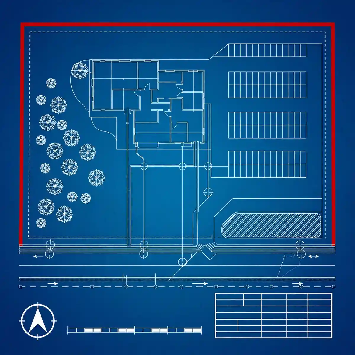
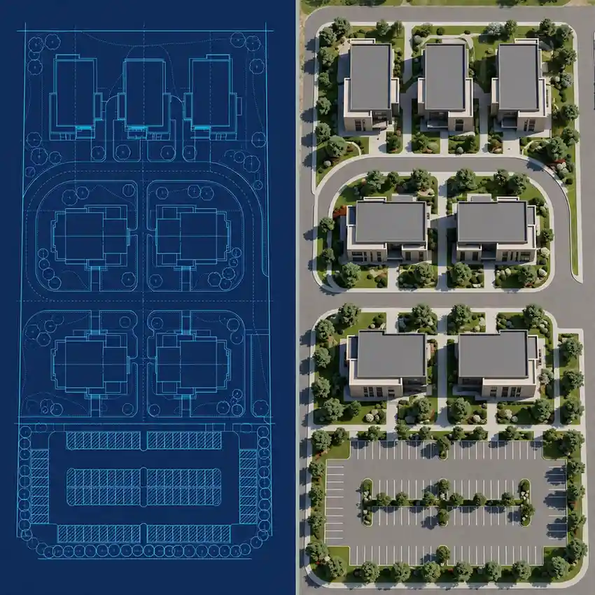
Getting that documentation right from the start requires working with a specialist who understands both the technical drafting standards and the planning submission requirements specific to your project type and jurisdiction. Equally important is understanding the full scope of what a properly executed site plan communicates: not just to the planning authority, but to engineers, contractors, utility providers, and investors who will rely on the same document throughout the project lifecycle.
Commissioning your site plan from a specialist 2D and 3D site plan rendering and drafting service gives developers, architects, and project managers the technically precise, authority-ready documentation they need – produced from any source material and delivered in the formats each project phase demands.
What is a 2D Site Plan? A Clear Definition for Developers
Before examining what a 2D site plan must include, it is worth establishing exactly what it is – and what it is not.
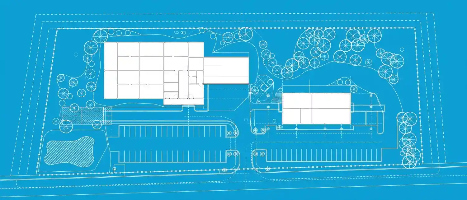
A 2D site plan is a scaled, top-down orthographic drawing that represents an entire property parcel as seen from directly above. It shows the relationship between the proposed or existing development and its immediate physical context: the boundaries of the land, the position and footprint of all structures on it, the access and circulation arrangements, the landscape and hard surfacing, and the infrastructure connections that serve the site.
Critically, a site plan operates at the site level, not at the building level. It does not show interior room layouts, structural details, or internal building systems – those are documented in floor plans, structural drawings, and building services drawings respectively. The site plan’s purpose is to communicate where and how the development sits within its plot and within its broader physical environment.
Quick Answer: A 2D site plan is a scaled, top-down drawing of an entire property showing building positions, boundaries, setbacks, access, utilities, and landscape features. It differs from a floor plan in that it documents the external site context, not the interior of buildings.
Understanding this distinction matters practically. Developers frequently conflate site plans and floor plans, submitting the wrong document type for a specific planning requirement or missing the site-level documentation that planning authorities require alongside interior building drawings. The fundamental differences between a site plan and a floor plan affect which document is needed at each stage of a development project and for each category of planning submission.
Why 2D Site Plan Design Quality Directly Affects Planning Outcomes
Planning authorities across all major jurisdictions treat the quality, completeness, and accuracy of the submitted site plan as a threshold test before substantive review begins. An application submitted with an incomplete or technically deficient site plan does not simply receive a lower evaluation score – it is typically marked as invalid and returned to the applicant before it enters the planning officer’s queue.
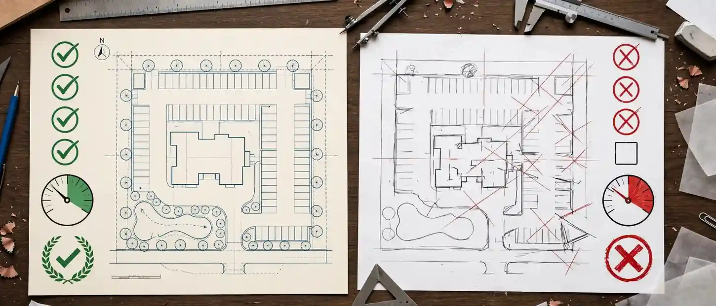
The practical consequences for developers are significant:
- Applications marked invalid restart the clock entirely, meaning statutory determination periods do not begin until a corrected resubmission is accepted
- Repeated invalidation cycles add weeks or months to project timelines, affecting financing arrangements, contractor programs, and project economics
- In competitive land markets, delayed approvals can result in the loss of option agreements, funding windows, or favorable interest rate periods
Research by getasiteplan.com identifies seven consistently recurring causes of site plan rejection: missing scale, unlabeled setbacks, inaccurate boundaries, omitted structures, undisclosed easements, inadequate drainage documentation, and a mismatch between the plan and the permit application form. Every one of these errors is technical, not substantive – meaning the development itself may be perfectly compliant with planning policy, but the application fails because the documentation does not meet drawing standards.
Similarly, Swale Borough Council’s planning application guidance – representative of the validation standards applied across English local planning authorities – lists the following as common reasons for application invalidity: the development site is not clearly outlined in red on the location plan; the scale bar is inaccurate or absent; the direction of north is not shown; drawings are not labeled clearly; and drawings are not drawn to a recognizable scale. These are entirely preventable errors.
Good 2D site plan design is therefore not a bureaucratic exercise – it is a direct risk management tool for every development project.
The Complete 2D Site Plan Design Checklist: Every Element a Developer Needs
The following checklist covers every element that a complete, authority-ready 2D site plan design should include. Requirements vary by jurisdiction, project type, and development scale, but this framework reflects the combined requirements of planning authorities across the UK, US, Canada, and Australia.
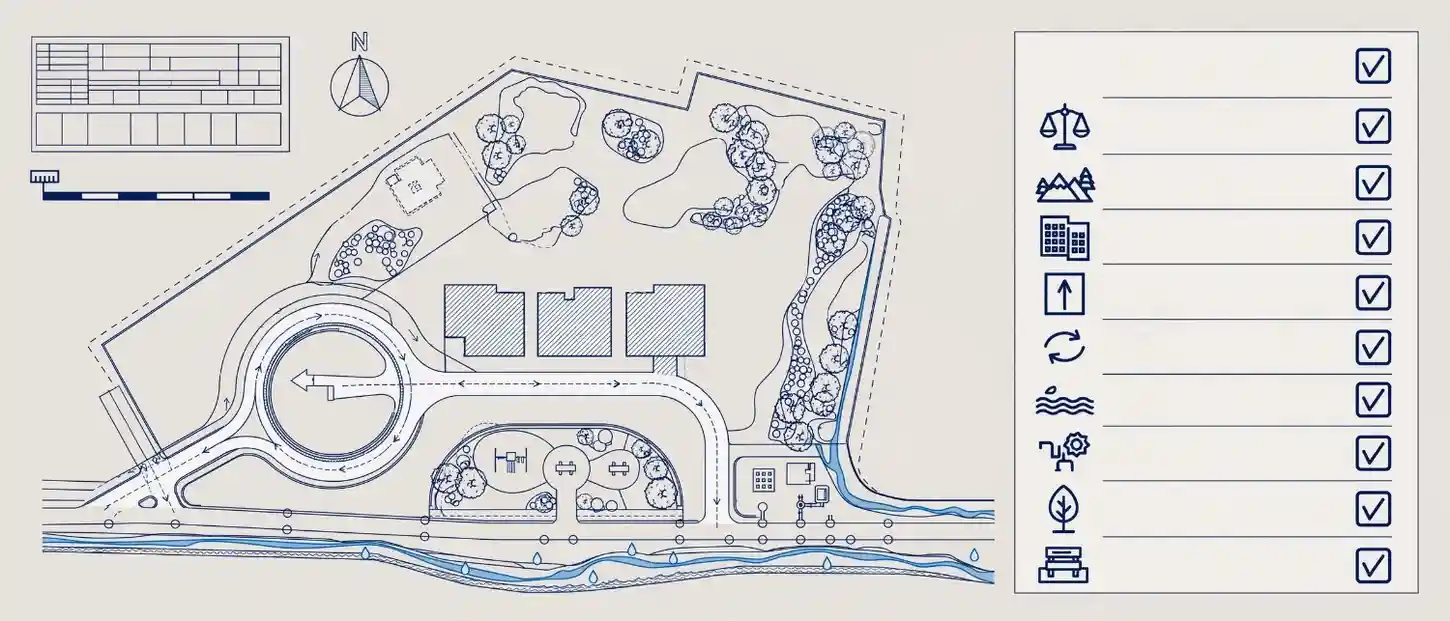
Category 1: Drawing Standards and Title Block

These elements appear on the drawing itself and establish its technical credibility and legal identification.
- Title block: Project name, site address, drawing title, drawing number, revision number, and date prepared
- Preparer’s credentials: Name, qualifications (architect, engineer, licensed surveyor), firm name, and contact details
- Metric bar scale: A graphical scale bar showing the drawing’s scale relationship to reality, enabling accurate measurement even if the drawing is reproduced at a different size. Textual scale notation alone (e.g., “1:200”) is insufficient as a standalone scale reference in many jurisdictions
- Drawing scale: The explicit ratio at which the plan is drawn. Standard scales for site plans are 1:200 or 1:500 for block plans and site layout plans; 1:1250 or 1:2500 for location plans showing the site in its wider context
- North arrow: A clearly drawn directional indicator showing true or magnetic north orientation of the plan
- Date of preparation and date of last revision: Both dates must appear, particularly important for resubmissions
Category 2: Property Boundary and Legal Framework

These elements define the legal extent of the site and its relationship to surrounding land ownership and rights.
- Property boundary lines: All property lines drawn from certified survey data, accurately dimensioned, and confirmed against official land registry records. These lines establish the legal extent of the developer’s control and are the reference from which all setback dimensions are measured
- Lot dimensions: The full perimeter dimensions of the property in metric units, annotated on each boundary line
- Site area: Total area of the property in square metres (or square feet for US jurisdictions), typically noted in the title block or as a separate annotation
- Easements: All legal easements crossing or bordering the property must be clearly shown, dimensioned, and labeled with their nature (drainage easement, utility easement, access easement, conservation easement). Undisclosed easements are a leading cause of site plan rejection
- Rights of way: All public rights of way crossing or adjacent to the site, including footpaths, bridleways, and public highways
- Adjoining land ownership: The ownership status of land immediately adjoining the site boundary – particularly relevant when the application affects shared boundaries or party walls
Category 3: Existing Conditions

Planning authorities require a clear picture of what exists on the site before assessing what is proposed. This category documents the pre-development conditions.
- Existing structures: All buildings, walls, fences, and structures currently on the site, shown accurately in footprint plan form with their relationship to property boundaries dimensioned
- Structures to be demolished: Any existing structures proposed for removal must be clearly identified, typically with a distinct linetype or cross-hatching convention with a corresponding legend
- Existing trees and significant vegetation: The position, spread radius, and species of all significant trees and shrubs, particularly those subject to Tree Preservation Orders (UK) or heritage tree protection (US/Australia). Authorities responsible for tree protection will not validate applications where affected trees are not disclosed
- Existing ground levels and topography: Spot heights or contour lines showing existing land levels, particularly where the site is sloping, where drainage design is a consideration, or where finished floor levels need to be established in relation to adjacent ground levels
- Existing access points and vehicle crossing positions
- Existing drainage infrastructure visible on the site
Category 4: Proposed Development and Structures

The core purpose of most site plan submissions is to document the proposed development accurately.
- Building footprints: The precise plan-view outline of all proposed buildings and structures, drawn at accurate scale. The footprint must be dimensioned both internally (overall building dimensions) and in relation to each property boundary line (setback distances)
- Setback dimensions: The measured distance from every proposed structure to each adjacent property line, clearly dimensioned. Setback requirements are a zoning compliance test, and failure to dimension them explicitly – even if the setback distances are technically compliant – is one of the most common causes of plan rejection
- Building heights: While elevations are typically separate drawings, the site plan should include annotation of the maximum proposed building heights where these are relevant to zoning compliance
- Proposed hard surfacing: All proposed paved areas including driveways, parking surfaces, terraces, and paths, shown in plan with materials annotated
- Proposed structures other than buildings: Retaining walls, fences, boundary walls, outbuildings, sheds, and any other permanent structures
Category 5: Access and Circulation

Access and movement arrangements are reviewed by multiple authorities simultaneously – highways engineers, parking compliance officers, and fire safety engineers all use the site plan as their reference.
- Vehicular access points: The precise position and width of all vehicular access points from the public highway, dimensioned to the carriageway edge
- Internal access roads and driveways: Layout, dimensions, and turning radii of all internal vehicle routes. Turning circles for refuse vehicles and emergency services are often required as specific annotations for larger developments
- Parking provision: Location, number, and dimensions of all parking spaces, including accessible parking bays. Many jurisdictions require parking provision to be stated as a total count adjacent to the parking area
- Pedestrian routes and footpaths: All pedestrian circulation routes through and around the site, with widths annotated
- Cycle parking and storage: Location and quantity for developments where cycling provision is a planning requirement
- Emergency vehicle access: Clear documentation of fire appliance access routes and turning areas, required for all but the smallest residential developments
Category 6: Drainage and Stormwater Management

Drainage is consistently identified as an area where site plans fall short of submission requirements, yet it receives detailed scrutiny from both planning officers and drainage engineers.
- Surface water drainage strategy: The proposed approach to managing rainwater runoff from the developed site, including the discharge route (to combined sewer, separate surface water sewer, soakaway, watercourse, or sustainable drainage system)
- Sustainable Drainage Systems (SuDS): For developments in many jurisdictions, SuDS are now a mandatory consideration. The site plan must show the location of any permeable paving, rain gardens, attenuation tanks, swales, or other SuDS features
- Finished floor levels: The proposed finished floor level (FFL) of all habitable buildings, dimensioned in relation to existing ground levels and any adjacent flood risk boundaries
- Flood risk zone: Where the site falls within or adjacent to a defined flood risk zone, the zone boundary must be shown on the site plan
- Existing drainage features: Inspection covers, gullies, drainage channels, watercourses, and ditches currently on or adjacent to the site
Category 7: Utility Connections and Services Infrastructure

- Water supply connection point and route
- Foul water sewer connection point: Position, invert level if known, and route to the public sewer network
- Surface water sewer connection point (where separate from foul drainage)
- Gas supply route and meter position
- Electrical supply route, substation position (for larger developments), and meter location
- Telecommunications and broadband infrastructure routes
- Street furniture and public utility assets: Lamp posts, overhead power lines, telegraph poles, and public utility manholes within or adjacent to the site, as these affect positioning of structures and may have minimum clearance requirements
Category 8: Landscape and External Amenity

- Proposed planting areas: Beds, borders, lawn areas, and tree planting positions, each labeled with the proposed species or simply as “soft landscaping” where detailed planting schedules are submitted separately
- Retained trees and vegetation: Trees and vegetation to be kept through the construction process, typically shown with a tree protection area annotation
- Boundary treatment: The type and height of all proposed boundary walls, fences, and hedges, annotated on each boundary
- External lighting positions: Particularly relevant for commercial and mixed-use developments or where lighting may affect neighbors or protected areas
- Bin storage and refuse collection areas: Position, access route for refuse vehicles, and dimensions of any enclosed bin storage structures
2D Site Plan Design by Project Type: What Changes
The core elements above apply to all site plan submissions, but the emphasis and specific additional requirements vary by project type. Understanding these variations prevents the common mistake of applying a residential site plan template to a commercial or mixed-use project.
| Project Type | Additional Specific Requirements | Standard Scale |
|---|---|---|
| Single-family residential | Septic system layout (where off-mains drainage), garage setbacks, accessory structure positions | 1:200 or 1:500 |
| Multi-unit residential / Apartments | Communal amenity space areas, refuse store dimensions, cycle storage, accessible unit positions | 1:500 |
| Commercial / Retail | Delivery access and loading bay dimensions, turning circles, service yard, disabled parking compliance | 1:500 |
| Industrial / Logistics | HGV turning circles, dock leveler positions, sprinkler tank positions, transformer substation | 1:500 or 1:1000 |
| Mixed-use development | Active frontage positions, ground-floor use zoning, public realm interfaces | 1:500 |
| Hotels / Hospitality | Drop-off areas, coach parking, plant room positions, service access separation from guests | 1:500 |
| Masterplan / Large-scale | Phasing boundaries, infrastructure zones, public open space areas, primary access strategy | 1:1000 or 1:2500 |
For hotel and hospitality developments specifically, the relationship between guest-facing spaces, service access, and public realm interfaces requires particularly careful site plan documentation. Poorly planned service access routes on a hotel site plan regularly generate objections from highways authorities, as conflict between delivery vehicles and hotel guests can create safety and operational issues that are very difficult to resolve after construction is complete.
2D Site Plan vs. 3D Site Plan: When Each Format Is Needed
A 2D site plan design serves the technical, legal, and compliance purposes described above. However, developers increasingly commission 3D site plan visualizations alongside the 2D documentation – not as a replacement for it, but as a communication tool for stakeholders, investors, and planning committees who are not trained to read technical drawings.
| Criteria | 2D Site Plan | 3D Site Plan Rendering |
|---|---|---|
| Planning authority submission | Required | Supplementary (increasingly common in pre-application discussions) |
| Building permit application | Required | Not required |
| Investor and board presentations | Functional | High impact |
| Pre-sales and marketing materials | Limited | Excellent |
| Construction and contractor use | Primary document | Reference only |
| Community consultation materials | Adequate | Very effective |
| Pre-application planning discussions | Standard | Increasingly expected for larger schemes |
| Legal and title documentation | Required (2D) | Not applicable |
The ability to commission a professionally rendered 2D and 3D site plan package from a single provider ensures dimensional consistency between the technical compliance document and the visual communication material – a common source of error when the two formats are commissioned separately.
Scale and Drawing Standards for 2D Site Plan Design
Scale is one of the most technically specific and rigorously enforced requirements in site plan design. Understanding the correct scale for each document type prevents one of the most common submission errors.
Location Plan Scale
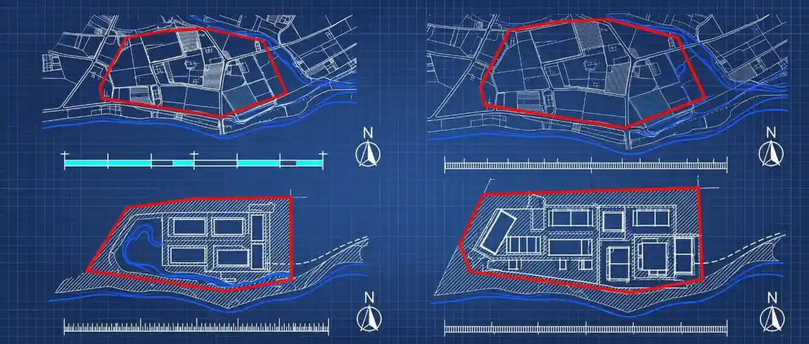
A location plan (also called a site location plan) shows the site in its wider neighborhood context. Standard scales are:
- 1:1250: The most common UK location plan scale. At this scale, a typical residential site occupies a small portion of an A4 or A3 sheet, with surrounding streets, buildings, and features clearly visible for several hundred metres in each direction
- 1:2500: Used for larger sites or where a wider context needs to be shown. In the US, location plans at 1:2400 (1 inch = 200 feet) are standard for many permit submissions
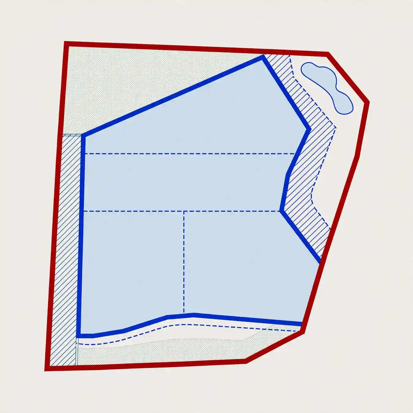
The location plan must show the application site boundary clearly outlined in red, with any land owned by the applicant but not included in the application outlined in blue.
Site Plan (Block Plan) Scale
The site or block plan shows the immediate site in detail. Standard scales are:
- 1:200: For smaller residential sites where detailed annotation of setbacks, access, and structures requires a larger drawing scale
- 1:500: The most widely used scale for residential and small commercial site plans across UK, US, and Australian jurisdictions. At 1:500, 1cm on the drawing represents 5 metres in reality
- 1:1000: For larger commercial sites, industrial developments, or masterplan submissions
According to buyaplan.co.uk, UK planning authorities most commonly require site plans at 1:200 or 1:500. All site plans must include a graphical bar scale, not just a written scale ratio, so that the document remains measurable even if printed at a non-standard size.
Critical Drawing Standards
- All dimensions must be in metric units for UK and most international submissions (feet and inches remain standard for US residential permit submissions)
- Linework must be clean, consistent, and reproducible in black and white – planning authorities print documents in greyscale and color-only communication of critical information will not survive the printing process
- Text must be legible at the printed scale, with minimum text heights specified in many authority style guides
- All abbreviations must be defined in a drawing legend
Common Mistakes in 2D Site Plan Design That Cause Delays and Rejections
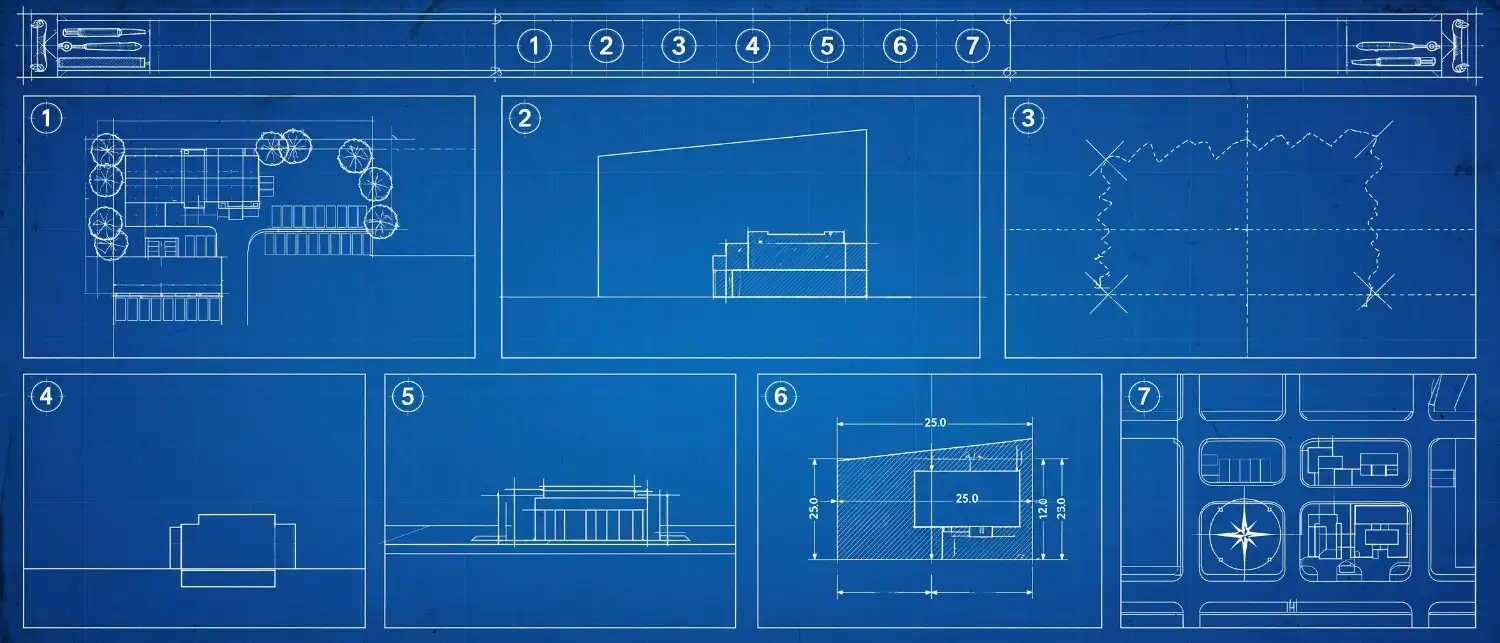
The following errors appear with high frequency in site plan submissions that are returned as invalid or that generate planning officer requests for additional information. Each one is entirely preventable with careful preparation.
Mistake 1: No graphical scale bar, or an inaccurate one
A text-only scale reference (e.g., “Scale 1:200”) does not satisfy most authority requirements because it becomes inaccurate when the document is reproduced at a different size. A graphical bar scale remains measurable regardless of reproduction size. Including both is best practice.
Mistake 2: Omitting setback dimensions
The setback distances from all proposed structures to every adjacent property boundary must be explicitly dimensioned on the drawing. It is not sufficient for the setbacks to be compliant – they must be labeled so that a reviewing officer can confirm compliance without measuring the drawing manually.
Mistake 3: Property boundary lines not derived from survey data
Property boundary lines estimated from memory, scaled from an online map, or reproduced from an old conveyancing plan rather than from a current certified survey are a consistent source of inaccuracy that creates legal risk as well as planning complications. For all but the most simple minor works applications, boundary lines should be derived from certified survey data.
Mistake 4: Missing or undisclosed easements
Legal easements that cross or border the property – utility easements, drainage easements, access easements – must appear on the site plan. Planning officers cannot assess the feasibility of a proposed development without knowing about constraints that restrict what can be built in specific zones of the site. Undisclosed easements discovered after approval can invalidate planning conditions.
Mistake 5: Showing only proposed development without existing conditions
Many submission requirements explicitly state that both existing and proposed conditions must be shown, either on the same drawing with clear differentiation or as a matched pair of drawings. Submitting only the proposed site plan without an equivalent existing conditions drawing is a standard cause of application invalidity.
Mistake 6: Inconsistency between the site plan and other submitted documents
The building footprint dimensions on the site plan must match the floor plans. The site address must match the application form. The site boundary must match the location plan. Inconsistencies between these documents – even minor ones – generate requests for clarification that pause the determination clock.
Mistake 7: Site plan not matching the specific permit type
Different permit types require different information on the site plan. A drainage permit submission requires more detailed drainage annotation than a basic building permit. A listed building consent application requires different contextual information from a change-of-use application. Using a generic site plan template without tailoring it to the specific submission type is a predictable source of requests for additional information.
Expert Tips: How Professional Developers Approach 2D Site Plan Commissioning
Developers with extensive planning experience approach site plan documentation differently from those encountering the process for the first time. Here are the practices that consistently separate efficient, smooth-running applications from those that experience unnecessary delays:
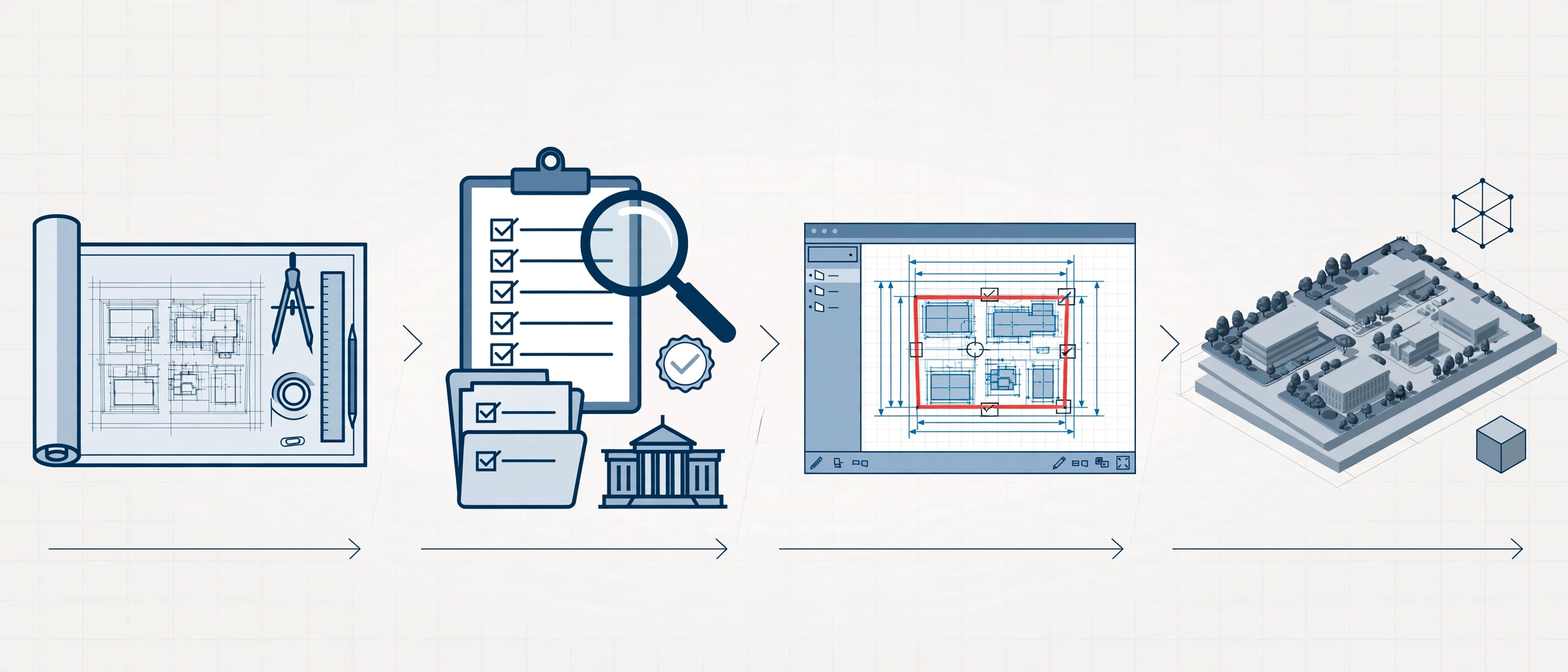
- Commission the site plan before drafting the planning statement. The spatial analysis required to produce an accurate site plan – surveying setbacks, identifying easements, mapping existing drainage – generates information that the planning statement needs to reference. Starting with the site plan produces a better planning statement, not just a better site plan.
- Check the local validation checklist before briefing your draftsperson. Every planning authority publishes a local validation checklist specifying exactly what their site plan submissions must contain, often going beyond national minimum requirements. Downloading and reviewing this document before commissioning the site plan prevents the common experience of having to revise a completed drawing to add a locally required element.
- Always show the site boundary in red. This convention is so universally established in UK and many international planning systems that its absence immediately signals to the reviewing officer that the plan has not been prepared by someone familiar with submission requirements.
- Dimension everything, even when it seems obvious. Reviewers are not permitted to assume compliance – they must be able to confirm it from the drawing. A setback that appears sufficient from visual inspection of a scaled drawing still needs to be dimensioned explicitly. An access road that looks wide enough needs its width in metres stated on the drawing.
- Keep your site plan in an editable format. Planning conditions frequently require minor amendments to site plans as a condition of approval. A site plan submitted as a flattened PDF or a scanned image creates significant cost and delay when amendments are required. Always retain the source file in an editable CAD or vector format.
- Pair your 2D site plan with a 3D rendering for major applications. For significant residential schemes, commercial developments, or any application likely to go before a planning committee, a photorealistic 3D site rendering prepared from the same source data as the 2D plan gives the committee a spatial context that technical drawings alone cannot provide. This has become increasingly standard practice in pre-application discussions with local authorities.
Reviewing professional samples of 2D site plan documentation before briefing your provider helps establish a clear quality standard and ensures the deliverable matches what the authority will expect.
How to Commission a Professional 2D Site Plan: Step-by-Step
- Obtain your site survey data. Commission a measured boundary survey from a licensed surveyor if current, accurate survey data is not already available. The survey data forms the legal foundation of the site plan – everything else on the drawing depends on the accuracy of the boundary coordinates.
- Download your local authority’s validation checklist. Before briefing any draftsperson, review the specific submission requirements of the planning authority to which you are applying. Note any locally required elements beyond the national standard requirements.
- Gather your existing documentation. Collect any existing architectural drawings, previous planning approvals, utility connection records, drainage surveys, and topographic data for the site. The more accurate source information you provide, the more accurate and compliant the resulting site plan will be.
- Define the scope of your required deliverables. Determine whether you need a location plan only, a site/block plan only, or both. Clarify whether existing conditions and proposed conditions need to be shown as separate drawings or on a single drawing with differentiation. Confirm whether you need a 2D plan alone, or a 2D and 3D combination.
- Brief your specialist site plan provider. Provide all source materials, the local authority checklist requirements, the project address, the proposed development description, and the target scale and paper size. A specialist provider can work from existing architectural drawings, AutoCAD files, PDF plans, hand-drawn sketches, or even a set of detailed measurements. The process of converting a rough sketch or measurement set into a professional site plan is a standard workflow for experienced drafting specialists.
- Review your draft carefully against the checklist. When the draft is delivered, check it systematically against the local authority validation checklist item by item. Confirm that all setback dimensions are present, all easements are shown, the scale bar is accurate, the north arrow is present, and the site boundary is clearly indicated. Request corrections before approving final delivery.
- Submit in the required file format. Most planning authorities now accept PDF submissions via online portals. Some require specific file size limits or resolution standards. Confirm the format requirements before commissioning the final deliverable to ensure your file meets portal upload requirements.
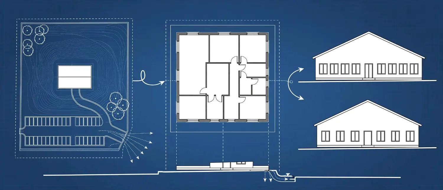
The Relationship Between Site Plans, Floor Plans, and Elevation Drawings
A complete planning application typically requires three categories of drawing working together: site plans, floor plans, and elevations. Understanding how they relate to each other – and how they must be internally consistent – prevents one of the most common sources of planning application delay.
| Drawing Type | Shows | Key Relationship to Site Plan |
|---|---|---|
| Site plan | The property and its context from above | The master reference document for all spatial relationships |
| Floor plan | Interior room layout of each building level | Building footprint on floor plan must match building footprint on site plan |
| Elevation drawings | Vertical external faces of each building | Building heights on elevations must be consistent with site plan level annotations |
| Sections | Vertical cut through the building and ground | Ground levels on sections must match existing ground level data on site plan |
| Roof plan | Top view of roof geometry and drainage | Roof area and drainage direction must be consistent with site plan drainage strategy |
When these drawings are produced by the same team working from the same source data, internal consistency is automatic. When they are produced by different parties – the architect doing elevations and floor plans, a separate draftsperson doing the site plan – dimensional inconsistencies regularly emerge that generate requests for information and planning authority queries.
This is one of the practical reasons why commissioning a professional 2D floor plan and site plan package from a single specialist provider produces more reliable, more consistent, and more efficiently approved documentation than splitting the work across multiple parties.
Review the full portfolio of professional 2D and 3D site plan samples to assess the drawing quality and annotation standards applied to every project – and find out why development professionals rely on The 2D3D Floor Plan Company for the documentation that every planning application depends on.
2D Site Plan Design for Specific Development Scenarios
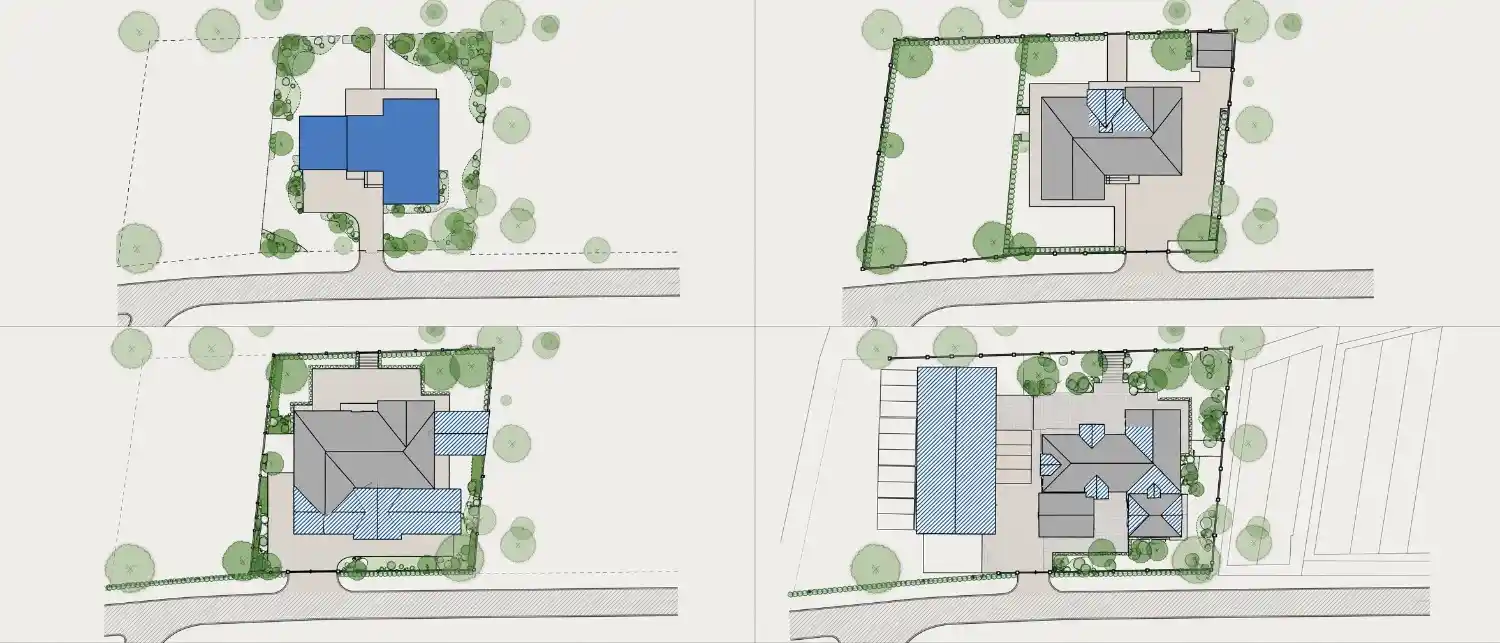
New Residential Build
For a new single-family home or small residential development, the site plan is typically the primary document by which the planning officer assesses compliance with:
- Minimum setback distances from all boundaries
- Lot coverage percentage (the proportion of the site area covered by building footprint)
- Parking provision requirements
- Garden area and amenity space provision
- Access and visibility splays from the public highway
The site plan for a new residential build should therefore include explicit annotation of the lot coverage calculation, the garden area calculation, and the parking provision count – not just the spatial data from which these could be calculated, but the calculations themselves as drawn annotations.
Permitted Development and Minor Works
Many minor works – extensions, outbuildings, fences, and decks – fall under permitted development rights and do not require a formal planning application. However, they typically still require a building permit (in the US) or building regulations approval (in the UK), both of which require a site plan submission.
For permitted development applications, the site plan may be simpler than a full planning submission, but it must still show: the precise footprint and dimensions of the proposed works; the setback distances from all boundaries; the existing site context sufficient to confirm the works are within the permitted development envelope; and the access to the works during construction.
Loft Conversions and Extensions
Extensions are among the most common site plan submissions made by property owners and small developers. The site plan for an extension must clearly distinguish between existing and proposed elements, with the extension footprint dimensioned separately from the existing building footprint, and with the resulting total lot coverage calculated and annotated.
Change of Use Applications
Change of use applications – converting commercial premises to residential, or retail to food and beverage, for example – may not involve any physical construction, but they still require a site plan showing the existing arrangement of the site, parking provision (which often changes with a change of use), and access arrangements.
Frequently Asked Questions: 2D Site Plan Design
What is a 2D site plan design?
A 2D site plan design is a professionally produced, scale-accurate, top-down drawing of an entire property that shows all existing and proposed structures in relation to the property boundaries, with dimensioned setbacks, access and circulation arrangements, drainage and utility connections, landscape elements, and all technical annotations required for planning authority submission. It is a distinct document from a floor plan (which shows interior room layouts) and serves as the primary spatial compliance document in planning, building permit, and development approval submissions.
What must a 2D site plan include for planning permission?
A complete 2D site plan design for planning permission must include: all property boundary lines dimensioned from certified survey data; setback distances from every proposed structure to each boundary line; the accurate footprint of all existing and proposed buildings; a north arrow; a graphical bar scale at an appropriate metric ratio (typically 1:200 or 1:500 for the site plan, 1:1250 or 1:2500 for the location plan); the site boundary clearly outlined in red; all legal easements and rights of way; access and parking arrangements; drainage and stormwater features; utility connections; significant trees and landscape features; a title block with project name, drawing number, preparer’s credentials, and preparation date. Local planning authorities publish validation checklists that may require additional elements specific to their jurisdiction.
What scale should a 2D site plan be drawn at?
The standard scales for a 2D site plan design are 1:200 or 1:500 for the block plan or site layout plan, and 1:1250 or 1:2500 for the location plan showing the site in its wider neighborhood context. The correct scale depends on the size of the site and the level of detail required by the submission type. All site plans must include a graphical bar scale, not just a written scale notation, so the drawing remains measurable if printed at a non-standard paper size.
What is the difference between a site plan and a floor plan?
A site plan shows the entire property from above, documenting how structures sit within their plot in relation to boundaries, access, utilities, and landscape. A floor plan shows the interior layout of a single building level, documenting room arrangements, wall positions, door and window openings, and interior dimensions. Both are required for most planning applications and building permit submissions, but they serve different purposes and are reviewed by different specialists within the planning and construction process.
Do I need a professional to produce my 2D site plan?
For minor works and simple residential permits in some jurisdictions, hand-drawn site plans that meet minimum accuracy standards may be accepted. However, for planning applications, building permits, and any development involving legal boundary data, easements, or compliance with specific setback regulations, a professionally produced site plan is strongly recommended. Most US jurisdictions require site plans to be stamped by a licensed architect, engineer, or surveyor. In the UK, planning authorities specify minimum drawing standards that hand-drawn plans rarely meet consistently. The risk of rejection, delay, and resubmission cost almost always outweighs the cost of professional production.
How long does it take to produce a professional 2D site plan?
Turnaround times depend on the complexity of the site, the availability of accurate source data, and the number of elements required. A straightforward residential site plan can typically be produced within 24-72 hours from accurate source materials. More complex commercial or multi-unit developments with detailed drainage, utility, and landscape requirements may require 3-5 business days. Expedited production is available from specialist providers for time-sensitive submissions.
Can I get a 2D site plan produced from a sketch or photograph of my existing plan?
Yes. A specialist site plan provider can work from hand-drawn sketches, photographs of existing printed plans, measured surveys recorded as handwritten notes, PDF architectural drawings, and AutoCAD files. The accuracy of the resulting site plan depends directly on the accuracy and completeness of the source information provided, which is why professionally measured survey data for the property boundaries is always the recommended foundation for any site plan submission.
What is the red line on a site plan?
The red line on a site plan – formally called the “red line boundary” – is a bold red outline drawn around the exact extent of the land to which the planning application relates. It is a mandatory convention in UK planning submissions and widely used in other jurisdictions. Any land within the red line boundary is considered to be under the applicant’s control for the purposes of the application. Land owned by the applicant but not included in the application should be shown outlined in blue. A missing or incorrectly drawn red line boundary is one of the most common reasons planning applications are returned as invalid.
Do site plans need to show underground utilities?
Where underground utility information is known – from utility record plans, site surveys, or previous planning documentation – it should be included on the site plan. For building permit submissions that involve ground excavation, utility connections, or drainage work, underground utility positions are often mandatory inclusions. Showing known underground utilities also protects the developer: undisclosed utility conflicts discovered during construction are expensive to resolve and may require design amendments that restart the planning process.
What is a site plan used for beyond planning applications?
A professional 2D site plan design serves multiple purposes beyond the initial planning or permit submission. During construction, it is the primary reference document for contractor site layout, temporary works positioning, and services connection coordination. Post-construction, it forms part of the property’s legal and facilities management record. For commercial properties, current site plans are required for lease documentation, building insurance valuations, fire safety assessments, and future alteration or development applications. For residential properties, a current site plan is frequently required for extension applications, boundary dispute resolution, and property sale conveyancing.
Precision in 2D Site Plan Design Protects Every Stage of Your Development
A properly executed 2D site plan design is not simply a planning requirement to be satisfied with the minimum acceptable effort. It is the spatial foundation document upon which every subsequent stage of a development project depends: from planning approval and building permit through to contractor programming, utility connection, and the permanent property record.
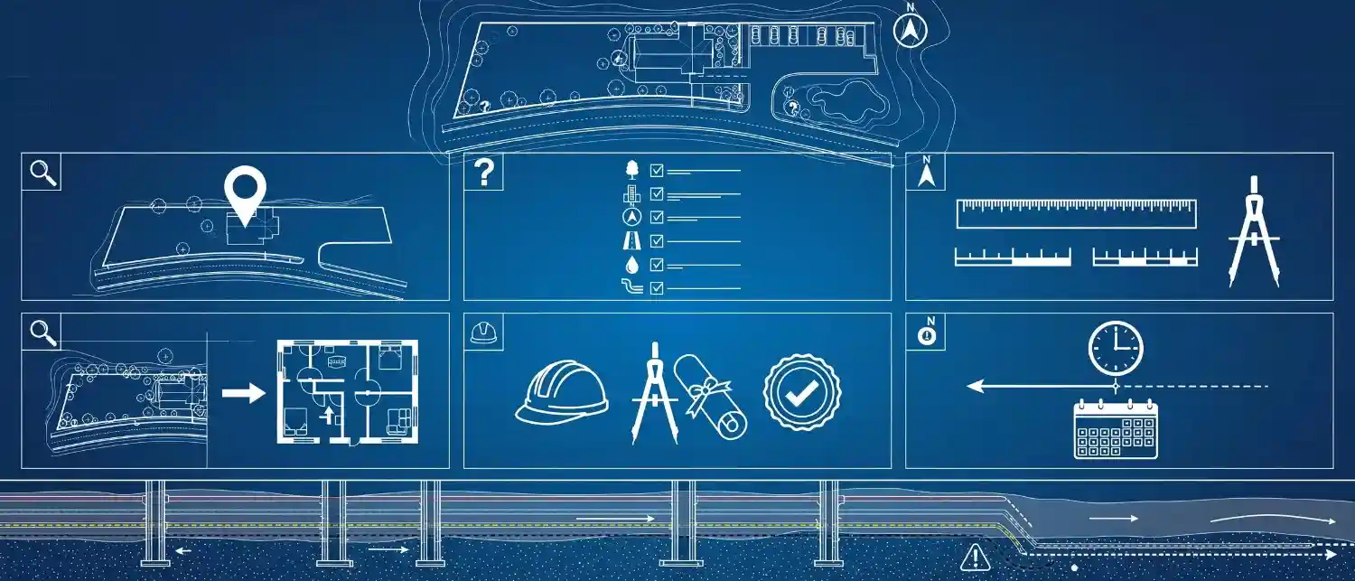
The difference between a site plan that clears the planning authority’s validation check first time and one that triggers an invalidation notice – and the weeks of delay that follow – almost always comes down to the completeness and technical precision of the drawing itself. Every element on the checklist in this guide exists because a planning authority, a building inspector, or a highways engineer needs that specific piece of information to do their job. Missing any one of them does not simply leave a gap in the drawing; it stalls the review process entirely.
For developers working with tight option periods, funding drawdown deadlines, or competitive planning windows, that delay has a direct financial cost that consistently exceeds the cost of getting the site plan right from the outset.
The expertise required to produce a complete, authority-ready site plan – one that anticipates the local validation checklist, includes every required element at the correct scale and drawing standard, and maintains dimensional consistency with all accompanying architectural drawings – is a specialist skill. It is worth commissioning from specialists who apply it every day.
Ready to commission professional 2D site plan documentation that passes validation, supports every project phase, and gives your development application its best possible start? Work with The 2D3D Floor Plan Company – a specialist team producing authority-ready 2D site plans, location plans, and 3D site renderings for developers, architects, and project managers worldwide.