
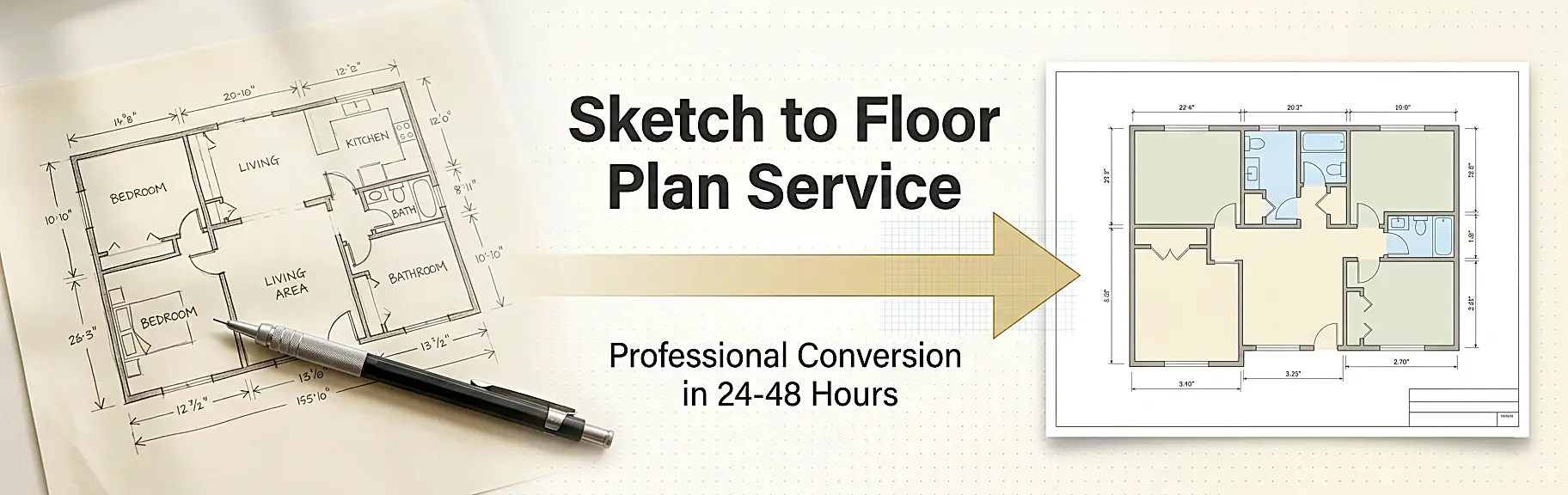
A professional sketch to floor plan service converts raw, hand-drawn spatial data – including rough wall outlines, approximate room dimensions, and annotated opening locations – into precision-drafted 2D CAD drawings or photorealistic 3D visualizations, following industry-standard drafting conventions such as ANSI/ISO symbology, scaled orthographic projection, and georeferenced layer structures. This conversion workflow moves through four core technical stages: sketch intake and dimensional interpretation, CAD drafting or BIM modeling, quality assurance against tolerances, and final delivery in client-specified file formats (DWG, PDF, PNG, or RVT). Whether you are an architect capturing a site survey, a real estate developer preparing marketing assets, or a homeowner planning a renovation, understanding this process is essential to getting output that is accurate, compliant, and publication-ready.
If you are looking for a trusted team that delivers this end-to-end process reliably, the specialists at The 2D3D Floor Plan Company provide fully managed 2D drafting, 3D modeling, and rendering services – handling everything from initial sketch assessment through to final export, with typical turnarounds of 24-48 hours.
Why Turning a Rough Sketch into a Professional Floor Plan Matters
A hand-drawn sketch is the starting point of almost every architectural or interior design project. It captures intent quickly. However, it cannot communicate spatial accuracy, regulatory compliance, or visual quality to contractors, clients, or property buyers on its own.
The numbers make this case clearly:
- A 2024 National Association of REALTORS® report identified floor plans as the third most important feature on real estate listing websites, ranked behind only photos and property details. (Source: NAR)
- Research compiled by Homes for Heroes found that 64% of home buyers want to see floor plans in a listing, and properties with floor plans spend up to 50% less time on the market. (Source: Homes for Heroes)
- According to a Zillow survey, 79% of prospective buyers are more likely to view a listing if it includes an appealing floor plan.
These numbers confirm that converting a rough sketch into a clean, professional floor plan is not just a drafting exercise – it is a direct revenue driver.
What Makes a Floor Plan “Professional”?
A professional floor plan is not simply a neater version of a sketch. It is a technically precise document defined by:
- Accurate scaled dimensions – typically 1:50 or 1:100 scale
- Standardized architectural symbols for walls, doors, windows, stairs, and fixtures
- Consistent line weights and layer management in accordance with CAD standards
- Annotated room labels, square footage callouts, and north orientation
- Compliance-ready formatting suitable for planning submissions, contractor tendering, or MLS listings
Understanding the difference between a raw drawing and a publication-ready plan is the first step toward commissioning the right output for your project.
Types of Input Sketches: What Can Be Converted?
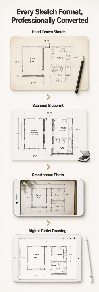
One of the most common questions clients ask is: “Can my sketch be converted?” The answer is almost always yes. Experienced drafting teams can work from a wide variety of source materials.
Hand-Drawn Sketches on Paper
The most common input format. These include napkin sketches, graph-paper layouts, architect field notes, and interior design concept drawings. Readable wall outlines and at least approximate room dimensions are the minimum requirement.
Scanned or Photographed Sketches
A high-resolution scan (300 DPI or above) or a clear smartphone photograph taken from directly above the sketch allows a drafter to trace and redraw with high precision. Avoid angled or shadowed shots; they introduce dimensional distortion.
Existing Printed Plans Without CAD Files
Older properties often have printed blueprints but no original CAD source file. A scan of these documents can be traced and redrawn as a fully editable DWG, which you can learn more about in this deep-dive on converting an image to a floor plan.
Rough Architectural or Builder Sketches
Site-measured drawings produced during property surveys, renovation assessments, or builder walkthroughs. These typically include hand-noted dimensions beside walls, which makes the conversion process significantly more accurate.
Digital Freehand Drawings (iPad / Tablet)
Sketches produced on Procreate, Adobe Fresco, or similar apps can be exported as high-resolution images and fed directly into the drafting workflow.
The Complete Sketch to Floor Plan Conversion Process: Step by Step
This is the core technical workflow that a professional sketch to floor plan service follows. Each stage builds on the previous one, and skipping any step risks producing an inaccurate or non-compliant output.
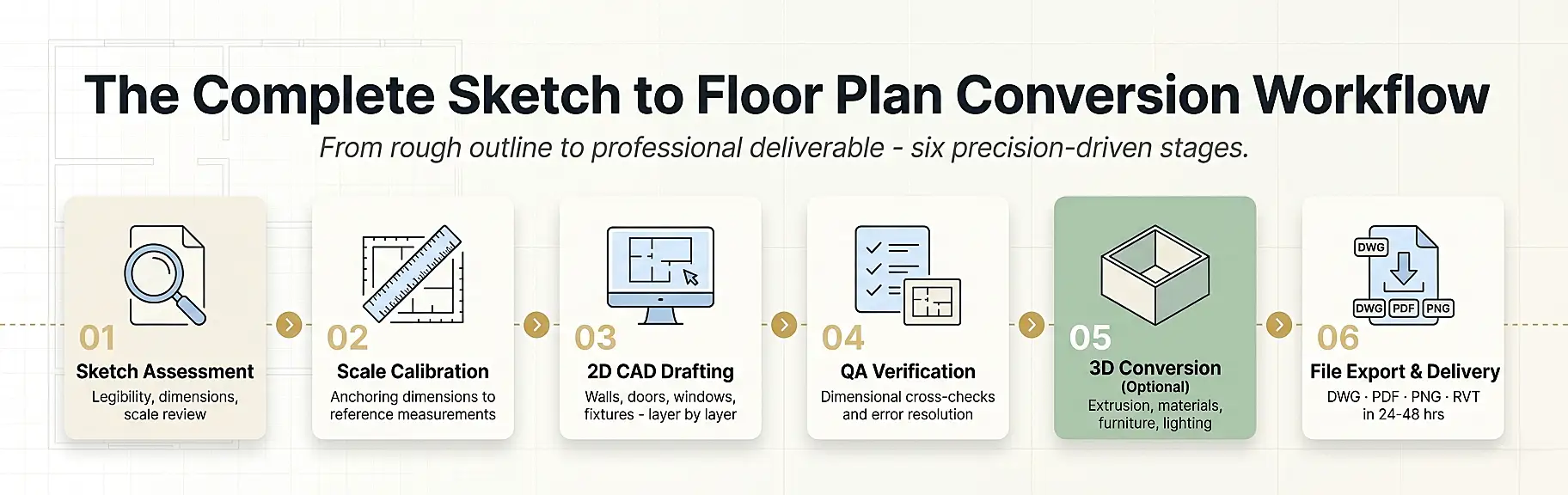
Step 1 – Sketch Assessment and Intake
Before any drafting begins, the team evaluates the submitted sketch for:
- Legibility: Are wall lines distinguishable from annotation lines?
- Dimensional completeness: Are room sizes noted, even approximately?
- Scale intent: Is there any reference measurement to anchor the drawing?
- Special features: Staircases, mezzanines, curved walls, bay windows
If critical dimensions are missing, a clarification request is issued to the client. Providing at least one or two key reference measurements – such as the total building footprint or a room’s known length – allows the drafter to proportionally reconstruct all other dimensions with good accuracy.
Pro tip: Before submitting your sketch, photograph it at a true orthogonal angle (directly above, no tilt) in natural daylight. Label every room with its intended use and add at least two overall dimensions.
Step 2 – Scale Calibration and Reference Setting
Once the sketch is accepted, the drafter imports it into CAD software (typically AutoCAD, Revit, or MicroStation) as an underlay. The sketch is then scaled to match any known reference dimension.
This calibration step is critical. Even a 2% scaling error on a 100 m² plan produces a 2 m² discrepancy in total area calculations – enough to trigger problems in planning applications or property appraisals.
Common calibration approaches include:
| Reference Type | How It Is Used |
|---|---|
| Known room dimension (e.g., 4.0m long bedroom) | Sets the global drawing scale |
| Door width (standard 900mm or 800mm) | Validates adjacent wall dimensions |
| Total building footprint | Cross-checks all internal partitions |
| Grid-paper square count | Establishes per-square scale ratio |
| Structural grid lines (for commercial projects) | Defines column spacing as a fixed reference |
Step 3 – 2D CAD Drafting
This is where the sketch becomes a floor plan. The drafter redraws every element of the layout using precision CAD tools, layer by layer:
- External walls – drawn first to establish the building envelope
- Internal partition walls – added at correct thicknesses (typically 100mm-200mm for residential)
- Door and window openings – placed with correct swing arcs and sill depths
- Stair geometry – drawn with correct tread, riser, and direction-of-travel arrows
- Fixed fixtures – bathroom suites, kitchen units, built-in wardrobes
- Annotation layer – room names, dimensions, area tags, north arrow, scale bar, title block
Each element sits on a dedicated layer, allowing contractors, planners, or rendering teams to switch layers on and off for their specific use case.
Step 4 – Dimensional Verification and QA
Before delivery, a quality assurance check compares the drafted plan against the original sketch and any provided reference dimensions. The QA process typically verifies:
- Overall building dimensions match the input reference
- All rooms close correctly (no gaps or overlapping walls)
- Door and window schedules are consistent
- Floor area calculations are correctly totalled
- Line weights and text styles meet the client’s specified standard
This stage is what separates a professional output from a raw CAD tracing. Skipping QA is the most common reason amateur conversions contain errors that only surface during construction or planning submission.
Step 5 – 2D-to-3D Conversion (Optional but Increasingly Standard)
Many clients now request both a precise 2D plan and a 3D floor plan conversion from the same source sketch. The 3D version is produced by extruding the 2D geometry, applying wall heights, adding furniture, materials, and lighting.
The 3D output dramatically improves client comprehension. Whereas a 2D plan requires spatial literacy to interpret, a 3D floor plan communicates room proportions and layout logic instantly – which is why real estate agents, property developers, and interior designers increasingly request both formats together. You can explore the practical difference in detail by reviewing the comparison of 2D and 3D floor plans.
Step 6 – File Export and Delivery
The final plan is exported in the formats specified by the client. Standard delivery packages typically include:
- DWG – editable CAD file for architects and contractors
- PDF – print-ready, high-resolution output for planning submissions
- PNG / JPEG – web-optimized images for real estate listings and marketing
- Revit RVT – for BIM-integrated project workflows
Turnaround for a standard residential floor plan conversion is typically 24-48 hours from sketch submission to final file delivery.
2D vs. 3D Output: Choosing the Right Format for Your Needs
| Use Case | Recommended Output | Why |
|---|---|---|
| Planning permission application | 2D CAD (PDF + DWG) | Regulatory bodies require dimensioned orthographic plans |
| Real estate listing (MLS / portal) | 2D colored + 3D | Maximizes buyer engagement and listing dwell time |
| Interior design presentation | 3D floor plan | Communicates furniture layout and spatial flow clearly |
| Construction tendering | 2D CAD (DWG) | Contractors require precise, layered drawing files |
| Developer marketing brochure | 3D high-quality render | Creates aspirational visual impact for off-plan sales |
| Renovation planning (homeowner) | 2D with dimensions | Practical reference for tradespeople and material estimates |
| Architect concept presentation | Both | Supports technical review and client approval simultaneously |
For a detailed walkthrough of which format suits your project best, the guide on 2D floor plan drawings for building new houses covers the planning and construction use cases in depth.
Common Sketch Quality Issues and How They Are Resolved
Even poorly prepared sketches can be converted successfully when a professional team handles the process. Here is how common problems are addressed:
Missing or Inconsistent Dimensions
Problem: The sketch shows rooms but provides no measurements, or measurements are inconsistent between adjacent rooms.
Solution: The drafter uses one or two anchor dimensions (if available) and proportionally reconstructs all others from the sketch geometry. For completely undimensioned sketches, the client is asked to confirm at least the total footprint length and width.
Illegible Line Work
Problem: The sketch has smudged lines, overlapping annotations, or unclear wall junctions.
Solution: The drafter interprets the intent using architectural convention and flags ambiguities for client confirmation before finalizing.
Non-Standard Symbols or Annotations
Problem: The client has used personal shorthand symbols that do not match standard architectural notation.
Solution: A legend or brief clarification call allows the team to correctly interpret every custom symbol. For reference on standard notation, the guide to floor plan symbols and legend is a useful resource.
Perspective or Isometric Sketches
Problem: The sketch has been drawn in perspective rather than true orthographic plan view, which distorts dimensions.
Solution: The drafter extracts dimensional intent from annotations and known reference elements, ignoring the perspective geometry and reconstructing the true orthographic plan from first principles.
Low-Resolution Scan or Image
Problem: The submitted image is too low in resolution to trace accurately.
Solution: The client is asked to rescan or rephotograph at a minimum of 300 DPI. Alternatively, if the sketch is simple enough, the drafter can work from key dimensions provided by text.
Expert Tips for Getting the Best Results from a Sketch Conversion
These are the workflow practices that consistently produce the fastest turnaround and most accurate output:
7 Expert Tips
For a Perfect Sketch SubmissionFollow these steps for the fastest turnaround and most accurate floor plan output.
Pro WorkflowInclude 2 Key Dimensions
Label Every Room
Mark Door Swings
Note Wall Thickness
Scan at 300 DPI
Specify Delivery Format
Order 2D + 3D Together
1. Always include at least two dimensions. Provide the total building length and width, or two room dimensions. This anchors the entire drawing.
2. Label every room. Write the intended use of each space directly on the sketch (kitchen, master bedroom, ensuite, etc.). This guides fixture placement in the drafted plan.
3. Mark door swing directions. A simple arc or arrow indicating which way a door opens saves a clarification cycle and prevents spatial conflicts in tight areas.
4. Note wall thickness for key walls. Exterior walls, party walls, and structural walls have different thicknesses. Marking these where known improves accuracy.
5. Submit at the highest resolution available. Scan at 300 DPI minimum. If photographing, use your phone’s highest quality setting in good natural light.
6. Specify your delivery format upfront. Telling the team whether you need DWG, PDF, or rendered PNG at the point of submission avoids revision requests later.
7. Request a 3D version alongside the 2D. Because both outputs are derived from the same CAD geometry, requesting both together is significantly more cost-effective than ordering them separately.
Sketch to Floor Plan Service: Typical Turnaround and Pricing
Understanding the cost and timeline of a professional conversion helps you plan your project budget and schedule accurately.
Turnaround Times by Project Type
| Project Type | Typical Delivery Time |
|---|---|
| Single-room sketch (studio / one room) | 12-24 hours |
| Standard residential (2-4 bedroom home) | 24-48 hours |
| Large residential (5+ bedrooms, multi-level) | 48-72 hours |
| Commercial floor plan (retail / office) | 2-4 business days |
| Hotel or multi-unit development | 3-5 business days |
| With 3D rendering added | +24-48 hours additional |
What Affects the Cost?
Pricing for a sketch to floor plan service varies based on:
- Complexity – number of rooms, levels, and unique architectural features
- Sketch quality – a clearly annotated sketch requires less interpretation time
- Output format – 2D only vs. 2D + 3D vs. full photorealistic rendering
- Turnaround speed – rush delivery typically carries a premium
- Revision allowance – the number of included revision rounds
For transparent, itemized pricing on both 2D and 3D floor plan services, the pricing page provides current rates broken down by project type. Specific 3D floor plan pricing is also available for combined conversion and rendering projects.
Applications by Industry: Who Uses a Sketch to Floor Plan Service?
Applications by Industry: Who Uses a Sketch to Floor Plan Service?
Real Estate Agents
Listing-ready 2D + 3D floor plans that reduce time on market.
Architects
Outsourced CAD drafting for concept and schematic design phases.
Interior Designers
Dimensionally accurate base plans for space planning and FF&E.
Contractors
Build-ready DWG files for material schedules and tendering.
Hospitality Developers
Multi-room plans for hotels, resorts, and serviced apartments.
Real Estate Agents and Property Developers
Converting a site-measured sketch into a polished 2D or 3D floor plan is now a standard step in property listing preparation. Research shows listings with floor plans receive significantly more engagement and sell faster. For a deeper look at the role of floor plans in real estate marketing, the article on how 3D floor plans help real estate agents sell properties is highly relevant.
Architects and Architectural Technicians
Architects frequently use sketch-to-plan services to accelerate the early design phase, outsourcing CAD drafting of concept sketches so their own team can focus on higher-value design and specification work.
Interior Designers
Interior designers use converted floor plans as the base for space planning, furniture layouts, and client presentations. A dimensionally accurate 2D plan ensures furniture selections are correctly sized before procurement.
Home Renovation Contractors
Builders and contractors working on extensions, loft conversions, or full refurbishments use converted plans to produce accurate material schedules, tender documents, and planning applications.
Hotel and Hospitality Developers
Large-scale hospitality projects – from boutique hotels to multi-storey resorts – require precise floor plans for room configuration, fire egress compliance, and FF&E (furniture, fixtures, and equipment) planning. The specialist area of hotel floor plan design involves unique requirements around corridor widths, back-of-house access, and accessibility compliance.
Property Technology (PropTech) Platforms
Digital real estate platforms increasingly require floor plan data as structured, machine-readable geometry. Converting sketches to CAD files enables ingestion into property databases, virtual tour platforms, and space management software.
Frequently Asked Questions (FAQ)
What is a sketch to floor plan service?
A sketch to floor plan service is a professional drafting and conversion workflow in which a trained CAD technician or architectural drafter takes a client’s hand-drawn, scanned, or photographed sketch and produces a precision-drafted 2D or 3D floor plan, delivered in industry-standard file formats such as DWG, PDF, or PNG.
How accurate can a conversion be if my sketch has no dimensions?
A conversion without any dimensions will be proportionally accurate – meaning the room relationships and layout will be correct – but the absolute scale cannot be guaranteed without at least one reference measurement. Providing even one overall dimension (such as the total building length) allows the drafter to scale the entire drawing correctly.
What file format should I request for my floor plan?
- For planning or building regulation submissions: PDF + DWG
- For real estate listings: PNG or high-resolution JPEG
- For interior design work: DWG or PDF with dimensions
- For 3D visualization: DWG as the base, plus rendered PNG or JPEG
How long does a sketch to floor plan conversion take?
Standard residential conversions typically take 24-48 hours from the point of sketch submission. Rush turnarounds of 12-24 hours are often available. Commercial projects and multi-level buildings may require 3-5 business days.
Can a rough sketch be converted into both a 2D and 3D floor plan?
Yes, and this is often the most cost-effective approach. Because the 3D model is built directly on top of the 2D CAD geometry, ordering both outputs together from a single sketch submission is typically faster and less expensive than commissioning them separately.
What is the difference between a 2D and a 3D floor plan?
A 2D floor plan is an orthographic top-down view showing wall positions, dimensions, and room labels. A 3D floor plan adds extruded walls, ceiling heights, furniture, materials, and lighting to create a perspective-view visualization. The detailed breakdown of what each format is and when to use it is covered in a dedicated resource.
Do I need to send a physical sketch, or can I submit a photo?
A clear, high-resolution photo taken directly above the sketch is perfectly acceptable and is the most common submission method. Scans at 300 DPI produce better results, but good smartphone photos in natural light are sufficient for most residential projects.
What software is used to convert sketches to floor plans?
Professional drafting services typically use AutoCAD for 2D plans and 3ds Max, SketchUp, or Revit for 3D conversions. Clients receive output files compatible with all major platforms. For an overview of relevant software options, the best 2D floor plan software guide is a useful reference.
Can a sketch of an existing property be used to create a floor plan for renovation?
Yes. This is one of the most common use cases. A builder or homeowner measures the existing property, produces a rough sketch of the current layout, and the conversion team drafts both an “as-built” plan and a proposed renovation layout from the same sketch submission.
Is a sketch to floor plan service suitable for commercial properties?
Absolutely. Commercial conversions – including offices, retail units, restaurants, and hotels – follow the same core workflow, with the addition of specific annotation requirements for fire egress, accessibility compliance, and MEP (mechanical, electrical, and plumbing) coordination zones.
From the First Line on Paper to a Plan That Works
Every professional floor plan begins as a rough sketch. The quality of the final output depends entirely on the accuracy of the conversion process and the expertise of the team handling it. A rigorous sketch to floor plan service workflow – covering dimensional calibration, precision CAD drafting, layer-managed output, and QA verification – transforms an informal drawing into a document that contractors can build from, planners can approve, and buyers can act on.
Whether your project is a single-room renovation, a multi-level residential development, or a commercial property refit, the investment in a professionally converted floor plan pays for itself immediately: in faster sales cycles, fewer construction errors, and cleaner client communications.
The 2D3D Floor Plan Company delivers the complete sketch to CAD pipeline – from your first rough outline to publication-ready 2D plans and photorealistic 3D renders – with guaranteed 24-48 hour turnaround and transparent pricing.
Submit your sketch and get your professional floor plan delivered today.