
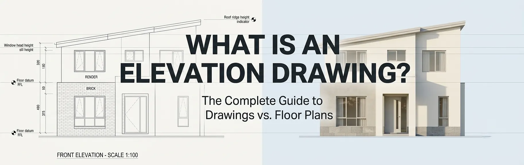
An elevation drawing is a scaled, two-dimensional orthographic projection showing one vertical face of a building or interior wall as viewed straight-on from the exterior or interior, capturing height, fenestration, facade materials, floor-level datums, and architectural detailing without perspective distortion. Unlike a floor plan – which is a horizontal section cut through a structure at approximately 4 feet above finished floor level – an elevation drawing communicates the vertical dimension of a design: rooflines, parapet heights, window-to-wall ratios, cladding specifications, and the overall aesthetic character of each facade. Together, these two drawing types form the foundational orthographic drawing set that architects, structural engineers, planning authorities, and contractors rely on to design, permit, and build any structure.
If you have ever looked at a set of architectural drawings and wondered which document tells you what the building actually looks like from the outside, the answer is the elevation drawing. Understanding what each drawing type shows – and when to use one over the other – is essential knowledge for property developers, real estate professionals, contractors, and anyone commissioning architectural plans.
Whether you are working with a professional 2D and 3D floor plan company to produce property marketing visuals or coordinating a full construction document set, knowing the role of an elevation drawing versus a floor plan will make every project decision sharper and faster.
Table of Contents
What is an Elevation Drawing? A Precise Definition
An elevation drawing is a flat, scaled, two-dimensional representation of one side of a building or one wall surface. It uses an orthographic projection system, meaning the viewer’s line of sight is perpendicular to the surface being drawn. There is no perspective, no foreshortening, and no vanishing point. Every element – doors, windows, columns, overhangs, and material boundaries – is shown at its true scaled height and width as it sits on that face.
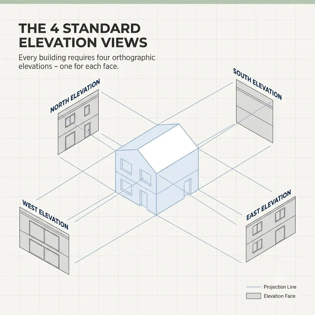
actice, architects produce a complete set of four primary exterior elevations for any rectangular building:
- Front elevation (also called the principal or street-facing elevation)
- Rear elevation
- Left side elevation
- Right side elevation
These are frequently referenced by compass direction – North Elevation, South Elevation, East Elevation, West Elevation – or by the building grid reference system used in larger commercial projects.
These are frequently referenced by compass direction – North Elevation, South Elevation, East Elevation, West Elevation – or by the building grid reference system used in larger commercial projects.
Interior elevation drawings follow the same logic but are applied to inside wall surfaces, making them particularly important for:
- Kitchen design (showing cabinetry heights, splash tile extents, and appliance locations)
- Bathroom layouts (showing tile patterns, fixture heights, and mirror placement)
- Feature walls, fireplaces, and custom joinery details
What Information Appears on an Elevation Drawing?
A professionally produced elevation drawing typically contains the following annotated elements:
| Element | Purpose |
|---|---|
| Finished floor level (FFL) datums | Establishes height of each floor relative to a fixed benchmark |
| Ceiling height dimensions | Confirms floor-to-ceiling clearances across all levels |
| Roof ridge and eave heights | Verifies compliance with local height restrictions |
| Window and door openings | Shows proportions, sill heights, and head heights |
| Facade material callouts | Specifies brick, render, cladding, timber, glass, etc. |
| Parapet and balustrade heights | Required for safety compliance documentation |
| Ground level and natural grade | Communicates cut and fill relationships |
| Section reference markers | Directs readers to cross-section drawings for further detail |
What is a Floor Plan? How it Compares to an Elevation Drawing
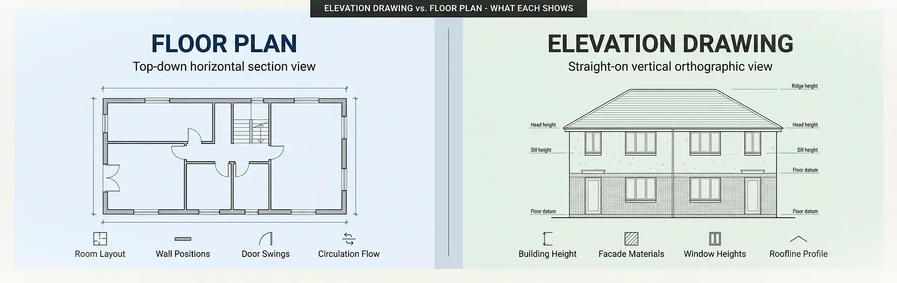
A floor plan is a horizontal section drawing. It is produced by making an imaginary horizontal cut through a building at roughly 1,200 mm (approximately 4 feet) above the finished floor level, then looking straight down at the exposed layout. This bird’s-eye view reveals:
- Room shapes, dimensions, and adjacencies
- Wall thicknesses and construction types
- Door swings and openings
- Window positions relative to room layout
- Furniture placement zones
- Structural column and beam grid lines
- Staircase configurations and circulation paths
Floor plans are the primary spatial planning tool. They answer the question: “How does the space work inside?” Elevation drawings answer a completely different question: “What does the building look like from the outside – and how tall is everything?”
You can explore detailed examples of professionally drafted floor plan drawings in our 2D floor plan samples library and compare them directly with exterior facade visualizations to see the contrast in information communicated.
Elevation Drawing vs. Floor Plan: Side-by-Side Comparison
The table below clarifies the core differences between these two critical drawing types:
| Attribute | Elevation Drawing | Floor Plan |
|---|---|---|
| View direction | Horizontal, straight-on | Vertical, top-down |
| Projection type | Orthographic – exterior/interior face | Horizontal section cut |
| Primary dimension shown | Height and width | Length and width |
| Depth shown | No | No |
| Information communicated | Facade, materials, roof, window heights | Room layout, walls, doors, circulation |
| Who uses it most | Architects, planners, facade contractors | Architects, builders, real estate agents |
| Required for building permits | Yes – standard requirement | Yes – standard requirement |
| Used in real estate marketing | Sometimes (as rendered facade image) | Very commonly (as a key listing asset) |
| Scale range | 1:50 to 1:200 (typical) | 1:50 to 1:200 (typical) |
| Interior version exists | Yes (interior elevation) | Yes (reflected ceiling plan variant) |
Types of Elevation Drawings Explained
Understanding the different categories of elevation drawings helps you order exactly the right deliverables for your project.
1. Exterior Elevation Drawings
These are the most widely recognized type. They present each external facade of a building, showing the complete vertical composition: materials, window and door openings, roofline profile, and how the building interfaces with its site levels.
Exterior elevations are a mandatory component of building permit applications in virtually every jurisdiction. Planning authorities use them to assess:
- Compliance with height limits and setback planes
- Visual impact on the streetscape
- Material and color compatibility with surrounding built form
- Compliance with design overlay requirements in heritage or special character zones
2. Interior Elevation Drawings
Interior elevations focus on individual wall surfaces within a room. Architects and interior designers produce these to detail custom elements that a floor plan alone cannot communicate. A kitchen elevation, for instance, shows the full run of upper and lower cabinets, the cooktop and rangehood relationship, splash tile extents, and the exact location of power outlets.
Interior elevations are particularly important for:
- High-specification residential kitchens and bathrooms
- Commercial fitout documentation
- Heritage building restoration work
- Retail and hospitality interior design
3. Sectional Elevation Drawings
A sectional elevation – sometimes called a section drawing – combines the logic of a section cut (cutting vertically through the building rather than horizontally) with an elevation view. It reveals the internal floor-to-floor heights, structural depth, stair configurations, and the relationship between spaces that cannot be read from either a pure floor plan or a pure elevation.
4. Reflected Ceiling Plan (Related Drawing Type)
While not strictly an elevation, the reflected ceiling plan shows the ceiling surface as if mirrored downward. It communicates lighting positions, diffuser and grille locations, ceiling height changes, and bulkheads – information that spans the gap between a floor plan and an interior elevation.
Why Elevation Drawings and Floor Plans Work as a Pair
Neither drawing type alone tells the full story of a building. Consider this scenario: a floor plan shows a room measuring 6 meters by 4 meters with a window centered on the north wall. But it cannot tell you:
- How high the window sill is from the floor
- Whether the window is a single panel or a ribbon of three panels
- What the external facade material is around the window
- Whether there is a projecting sill, an architrave, or a frameless flush glazing system
The elevation drawing answers every one of these questions. Together, the floor plan establishes the horizontal logic of the space, while the elevation drawing establishes the vertical logic of the facade.
This is why every professional architectural drawing set – whether for a residential addition, a new commercial building, or a mixed-use development – contains both document types. They are complementary, not interchangeable.
For those working in real estate, understanding how a 2D floor plan for property listings drives buyer engagement is equally important – and our guide to 2D floor plans for real estate listings and conversions covers that in detail.
How Elevation Drawings Are Produced: A Step-by-Step Process
Step 1: Establish the Floor Plan Base
An elevation drawing is always derived from the floor plan geometry. The width of each elevation corresponds directly to the building width shown in plan. Architects project vertical lines upward from the plan corners to establish the outer wall positions in the elevation.
Step 2: Set Floor Level Datums
Using structural drawings and site survey data, the draftsperson establishes the finished floor level (FFL) for each storey. These horizontal datum lines form the structural backbone of the elevation drawing.
Step 3: Project Heights from Sections or Specifications
Window head heights, ceiling heights, parapet heights, and roof ridge heights are projected in from cross-section drawings or taken directly from specifications. This ensures the elevation accurately represents the three-dimensional building.
Step 4: Add Facade Elements
Doors, windows, columns, pilasters, cladding panel joints, balustrades, and decorative elements are drawn at their correct scaled positions within the elevation composition.
Step 5: Apply Material Hatching and Callouts
Each material zone receives a standard hatch pattern (brick, masonry, timber, glazing, etc.) along with a written specification callout or a keynote reference to the material schedule.
Step 6: Add Dimension Lines and Level Markers
Vertical dimension strings and elevation datums are added to communicate critical height measurements clearly. Horizontal dimensions may also appear to confirm fenestration centerline positions.
Step 7: Apply Title Block, Scale Bar, and Reference Notation
The completed elevation is titled (e.g., “North Elevation – Scale 1:100”), a graphic scale bar is added, and section markers or detail bubbles reference related drawings within the document set.
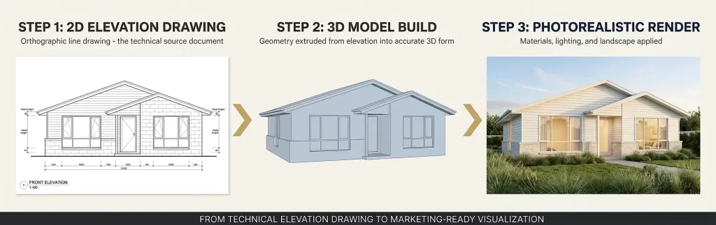
Converting 2D Elevation Drawings to 3D Exterior Renderings
One of the most powerful workflows in modern architectural visualization is taking a flat 2D elevation drawing and transforming it into a photorealistic 3D exterior render. This process allows clients, investors, and planning authorities to see exactly what a building will look like in its real environment, complete with:
- Realistic material textures and lighting
- Landscaping and context
- Shadow studies
- Time-of-day variations
If you have existing 2D elevations and want to bring them to life, our 2D elevation to 3D exterior rendering conversion service does exactly that. Similarly, our 3D house front design service specializes in turning elevation drawings into compelling facade visualizations for marketing and planning purposes.
This process is particularly valuable for:
- Off-the-plan property sales
- Planning and development applications
- Client presentations during the design development phase
- Social media and digital marketing campaigns for new developments
Common Mistakes When Creating or Using Elevation Drawings
Understanding where errors typically occur helps you avoid costly rework and project delays.
Mistake 1: Treating the Elevation as a Decorative Sketch
An elevation drawing is a technical, legally referenced document. It must be drawn to scale with accurate dimensions, not used as a loose artistic impression. Inaccurate elevations submitted with permit applications are one of the most common causes of resubmission delays.
Mistake 2: Ignoring the Relationship Between Plan and Elevation
Every horizontal dimension on an elevation must correspond exactly to the geometry shown in the floor plan. A mismatch between plan and elevation – even by a small margin – creates coordination conflicts in the field that are expensive to resolve.
Mistake 3: Omitting Ground Level and Natural Grade Lines
Many elevation drawings show the building floating above an undefined datum. Clearly showing finished ground level, natural grade, and any retaining walls or level changes is essential for understanding how the building relates to its site.
Mistake 4: Overloading the Elevation With Interior Information
An exterior elevation should communicate the external face only. Including interior elements – such as furniture or internal partitions visible through windows – is misleading and adds unnecessary confusion for contractors reading the document.
Mistake 5: Using Inconsistent Scales Across the Drawing Set
If the floor plan is drawn at 1:100 and the elevation is drawn at 1:200 without clear notation, comparisons between documents become unreliable. All drawings in a set should use consistent scales, or scale differences must be clearly labeled.
Mistake 6: Forgetting Interior Elevations for Complex Spaces
Many projects produce thorough exterior elevations but neglect interior elevations entirely. For kitchens, bathrooms, custom joinery, and heritage restorations, interior elevation drawings are not optional – they are essential.
Expert Tips for Getting the Most Out of Elevation Drawings
Tip 1: Commission Both Floor Plans and Elevations Together
Ordering floor plans and elevations as a coordinated set – rather than separately at different times – ensures geometric consistency between the two drawing types. This reduces coordination errors and produces a more reliable document set.
Tip 2: Use Elevation Drawings Early in the Design Process
Elevations are most valuable as a design exploration tool when introduced alongside early-stage floor planning, not as an afterthought after the spatial layout is fixed. Many facade proportion issues, awkward window alignments, and roofline conflicts only become visible in elevation.
Tip 3: Match Your Elevation Scale to Your Level of Detail
For planning permit submissions, a 1:100 or 1:200 scale is typically sufficient. For detailed facade specification – especially for complex cladding systems, curtain walls, or intricate heritage detailing – a 1:50 or 1:20 scale may be required to communicate the information accurately.
Tip 4: Always Include a North Point and Orientation Label
Labeling elevations by compass direction (North Elevation, South Elevation, etc.) removes ambiguity during construction. Contractors and subcontractors on site can then orient themselves to the drawing without needing to reference the floor plan every time.
Tip 5: Leverage 3D Visualization to Communicate Elevations to Non-Technical Clients
Technical elevation drawings are excellent communication tools between design professionals. However, clients without architectural training can struggle to interpret them. Pairing your elevation drawings with a 3D exterior rendering, or exploring our 3D exterior rendering services, bridges this communication gap immediately.
When Do You Need an Elevation Drawing?
Here is a clear guide to the most common scenarios that require elevation drawings:
Building Permit Applications: Nearly every building permit application requires a complete set of exterior elevations. Planning authorities need elevation drawings to verify height compliance, material selection, and streetscape impact.
New Construction Documentation: Any new building, from a residential extension to a commercial tower, requires elevation drawings as part of the full construction document set. Facade contractors, window suppliers, and cladding installers all work from elevation drawings during construction.
Real Estate Development Marketing: While floor plans dominate property marketing, elevation drawings provide the source geometry for photorealistic 3D exterior renders used in off-the-plan campaigns and project marketing suites.
Heritage and Conservation Applications: Restoration and renovation work on heritage-listed buildings requires precise measured elevation drawings of the existing facade as a baseline document. This is also sometimes called an “as-built elevation.”
Interior Design Documentation: Kitchen and bathroom fitout contractors, custom joinery manufacturers, and tile contractors all work from interior elevation drawings to manufacture, supply, and install elements to the correct heights.
Feasibility and Development Assessment: Early-stage elevation sketches help developers test building envelope options, assess massing, and understand visual impact before committing to detailed design fees.
Elevation Drawing vs. Floor Plan: Which Do You Need?
The answer is almost always: both. They serve fundamentally different purposes and answer different questions about the same building. Here is a quick decision guide:
| If you need to know… | Use this drawing type |
|---|---|
| Room sizes and spatial layout | Floor plan |
| Building height and roofline profile | Elevation drawing |
| Door and window positions in the room | Floor plan |
| Door and window heights above floor level | Elevation drawing |
| How circulation flows between spaces | Floor plan |
| How facade materials are arranged vertically | Elevation drawing |
| Furniture and equipment layout | Floor plan |
| Parapet, balustrade, and sill heights | Elevation drawing |
| Compliance with setback requirements (horizontal) | Floor plan + site plan |
| Compliance with height restrictions | Elevation drawing |
For real estate professionals specifically, understanding the difference between 2D floor plans and 3D floor plans is equally important alongside knowing when elevation drawings add value to a property marketing package.
Elevation Drawings in the Context of a Full Architectural Drawing Set
To understand elevation drawings fully, it helps to see where they sit within a complete set of architectural construction documents. A standard residential drawing set for a new home typically includes the following:
- Site plan – shows the property boundaries and building position on the land
- Floor plans – shows the internal layout of each level
- Roof plan – shows the roof structure and drainage slopes from above
- Exterior elevation drawings – shows all four external facades
- Building sections – shows vertical cuts through the building revealing internal floor and ceiling heights
- Interior elevation drawings – shows specific wall surfaces inside the building
- Construction details – shows enlarged drawings of specific junctions and connections
- Schedules – lists doors, windows, finishes, and fixtures in tabular format
Each of these drawing types is interdependent. The elevation drawing cannot be read in isolation; it is part of a coordinated set where information flows between all documents.
According to Vectorworks’ architectural guide to elevation drawings, always including accurate scale and dimensions ensures the design remains clear and interpretable across the entire project team.
The American Institute of Architects (AIA) and the Royal Architectural Institute of Canada (RAIC) both specify elevation drawings as a mandatory component of standard architectural drawing sets for construction documentation.
For practical guidance on reading architectural floor plan symbols – which also applies to how symbols appear in elevation drawings – our floor plan symbols and legend guide is an excellent companion resource.
Frequently Asked Questions
What is an elevation drawing in simple terms?
An elevation drawing is a flat, scaled, straight-on view of one side of a building or wall. It shows the vertical dimension of the structure: how tall things are, where windows and doors sit relative to floor and ceiling levels, what materials cover the facade, and what the roofline profile looks like. Unlike a floor plan, which looks down from above, an elevation drawing looks directly at a face of the building.
What is the difference between a floor plan and an elevation drawing?
A floor plan is a horizontal section cut through a building viewed from above, showing room layout, wall positions, and spatial flow. An elevation drawing is a vertical, straight-on view of one external or internal face of a building, showing heights, materials, and facade composition. Both are orthographic projections, but they reveal completely different information about the same structure.
How many elevation drawings does a typical building project require?
Most projects require a minimum of four exterior elevation drawings – one for each face of the building (front, rear, left side, right side). Complex buildings with irregular floor plans may require additional elevation drawings for each distinct facade change. Interior elevation drawings are produced separately for rooms with custom joinery, cabinetry, or special finishes.
Are elevation drawings required for a building permit?
Yes. In most jurisdictions, a complete set of exterior elevation drawings is a mandatory requirement for residential and commercial building permit applications. Planning authorities use elevations to verify height compliance, facade material selection, and visual impact on the surrounding built environment. According to Evolution Drafting’s building permit guide, site plans, floor plans, and elevations form the core required drawing set for most residential permits.
Can an elevation drawing be converted to a 3D render?
Yes, and this is one of the most common workflows in contemporary architectural visualization. A 2D elevation drawing provides the geometric source information needed to build an accurate 3D model, which can then be rendered with photorealistic materials, lighting, and landscape to produce a compelling visualization for client presentations, marketing, or planning submissions.
What is an interior elevation drawing used for?
An interior elevation drawing shows one wall surface inside a room, viewed straight on. It is used to communicate cabinetry heights, tile extents, fixture positions, and other vertical details that cannot be shown adequately in a floor plan. Interior elevations are particularly important for kitchens, bathrooms, custom joinery, and any space where vertical surface specification is critical.
What is the difference between an elevation drawing and a section drawing?
An elevation drawing shows the external face of a building or an internal wall as viewed from outside that surface. A section drawing cuts through the building vertically and shows the internal structure, floor-to-floor heights, and spatial relationships of rooms stacked above one another. Both use orthographic projection, but a section reveals what is inside the building structure, while an elevation shows only the surface face.
What scale are elevation drawings typically drawn at?
Elevation drawings are most commonly produced at scales of 1:100 or 1:50 for residential projects. Larger commercial projects may use 1:200 for overall building elevations. Detail elevations – showing complex junctions, heritage detailing, or custom facade systems – may be drawn at 1:20 or 1:10 to communicate the required level of precision. As noted by engineering publisher TPUB, a typical elevation uses the same scale as its corresponding floor plan, commonly 1:48 (1/4 inch = 1 foot) in imperial practice.
Mastering Elevation Drawings for Better Project Outcomes
What is an elevation drawing? At its core, it is the vertical counterpart to the floor plan: a technically precise, scaled, orthographic representation of a building’s face that communicates everything the top-down plan view cannot. Height, materials, roofline, fenestration proportions, and facade character all live in the elevation drawing.
Floor plans and elevation drawings are not competing documents – they are complementary partners in a coordinated drawing set. Every professional project needs both. Floor plans answer “how does the space work?”, while elevation drawings answer “what does it look like from the outside and how tall is everything?”
For property developers, real estate agents, architects, and construction professionals, understanding when each drawing type applies – and how they interact – is a foundational competency that pays dividends across every project phase.
Whether you need precise 2D elevation drawings for a permit submission, want to understand how your floor plan relates to your building’s exterior appearance, or are ready to convert existing elevation drawings into stunning photorealistic 3D exterior renders, the expertise to deliver all of these is available in one place.
Ready to bring your elevation drawings and floor plans to life? Explore our full range of 2D floor plan, 3D floor plan, and exterior rendering services and request a custom quote for your next project – our team delivers publication-quality architectural visuals that accelerate your sales, approvals, and design decisions.