
If you have ever stared at a blueprint and felt completely lost, you are not alone. Floor plan symbols and legend markings can look like a foreign language at first – but once you understand the visual shorthand, any floor plan becomes instantly readable. Whether you are a first-time homebuyer reviewing a property layout, a property investor evaluating a development, or simply trying to understand what those small squares, dashed lines, and arrows actually mean, this guide covers everything.
In this complete reference, you will learn what every common floor plan symbol means, how legends work across different plan types, and how to confidently interpret both simple sketches and professional architectural drawings. By the end, reading floor plans will feel as natural as reading a map.
What is a Floor Plan Legend?
A floor plan legend (also called a floor plan key) is a reference box – usually placed in a corner of the drawing – that explains what each symbol, line type, pattern, or notation represents in that specific plan.
Think of it exactly like a map legend. Just as a road map uses colored lines to distinguish highways from local roads, a floor plan uses standardized symbols to represent walls, doors, windows, fixtures, and more.
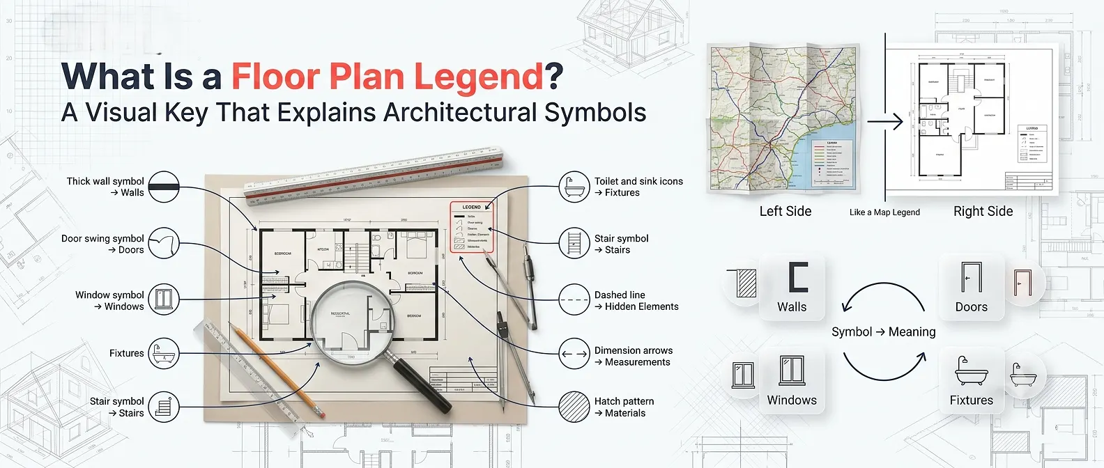
Quick definition: A floor plan legend is a visual key that translates the abstract symbols and shorthand in an architectural drawing into plain, understandable labels.
Not all floor plans use identical symbols; conventions can vary slightly by country, software, or architectural firm. That is precisely why the legend matters – it gives you the ground rules for that specific drawing.
Why Floor Plan Symbols Matter
Understanding floor plan symbols and legend notation is valuable for several practical reasons:
- Homebuyers can verify that rooms, storage, and fixtures match what is described verbally.
- Property developers can review layouts without waiting for explanations from architects.
- Real estate agents can communicate more effectively with clients about space and flow.
- Interior designers use symbol knowledge to plan furniture placement and traffic patterns.
- Contractors and builders rely on symbol accuracy to avoid costly construction errors.
When you work with a professional 2D floor plan service, the drawings you receive follow established symbol conventions – making this knowledge directly applicable to real projects.
The Main Categories of Floor Plan Symbols
Floor plan symbols generally fall into six major categories. Understanding each one builds your ability to read any plan, regardless of scale or complexity.
1. Wall Symbols
Walls are one of the most important elements in any floor plan because they define the shape and layout of a building. They are typically represented by parallel lines, which help distinguish walls from other architectural features.
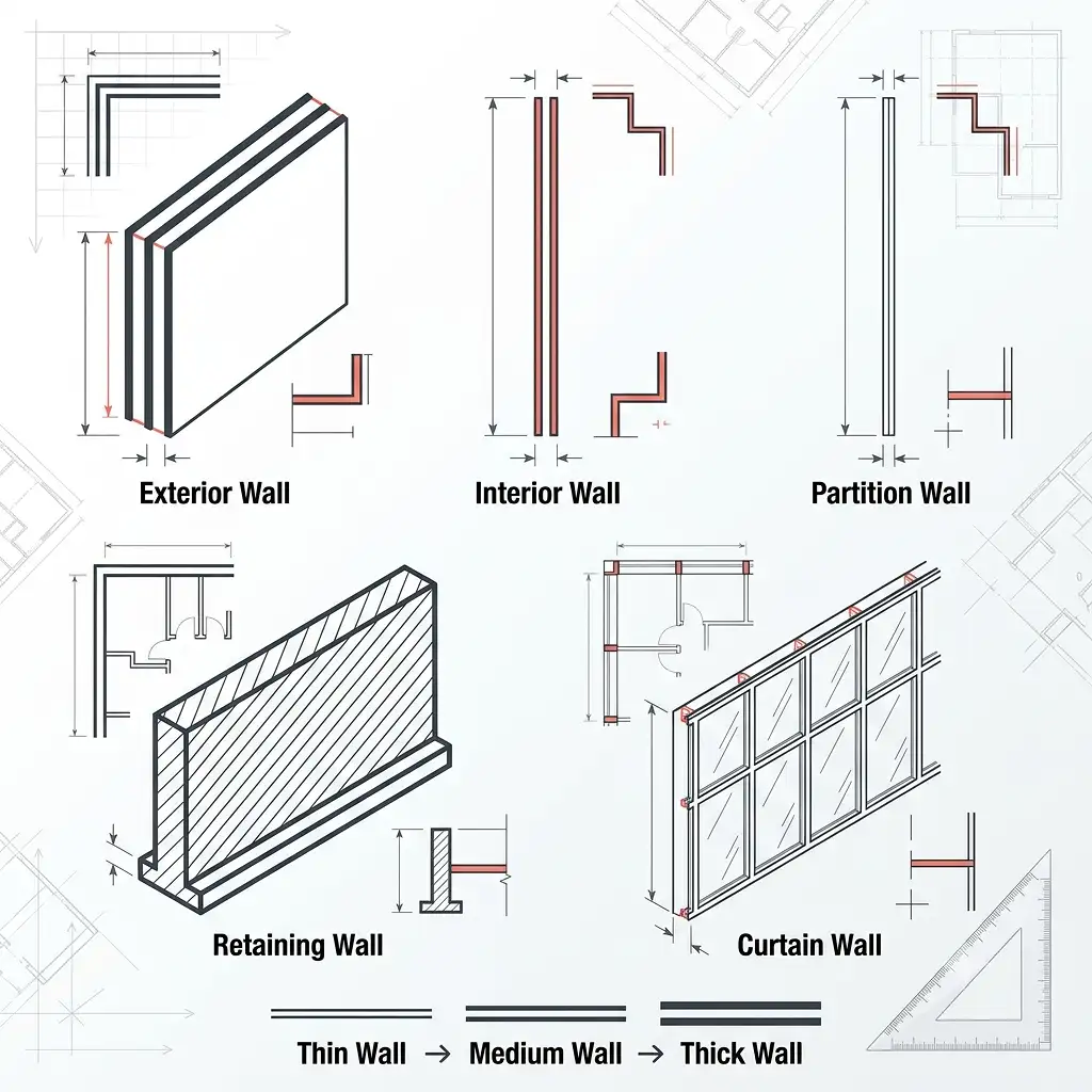
The thickness of these lines indicates the wall type. Thicker lines usually represent exterior or load-bearing walls, while thinner lines are used for interior and partition walls. Understanding wall symbols makes it easier to interpret the structure and room arrangement of a floor plan.
Exterior Wall – Used for the outer boundary of a building and typically represents load-bearing construction. Interior Wall – Used to divide rooms and separate spaces inside the building. Partition Wall – A non-load-bearing wall used to create internal divisions without supporting structural loads. Retaining Wall – Commonly used for structural support, especially in basements and areas with varying ground levels. Curtain Wall – Frequently used in commercial buildings to create large glazed facades and modern exterior designs.
Tip: The thicker the line pair, the more structurally significant the wall typically is.
Wall Types & Their Uses
| Wall Type | Symbol Description | Typical Use |
|---|---|---|
| Exterior Wall | Thick parallel lines (wider gap) | Outer boundary of building |
| Interior Wall | Thinner parallel lines (narrower gap) | Room dividers inside |
| Partition Wall | Very thin or single line | Non-load-bearing dividers |
| Retaining Wall | Hatched or solid thick lines | Structural/basement walls |
| Curtain Wall | Thin line with glass pattern | Commercial glazed facades |
2. Door Symbols
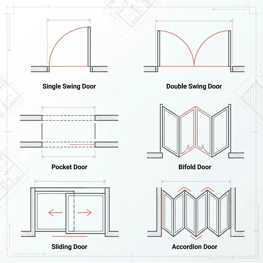
Doors are shown as a straight line (the door panel) plus an arc (the swing path). This tells you both where the door is located and which direction it opens – critical for furniture placement.
Common door symbols include:
- Single swing door: One straight line plus a quarter-circle arc
- Double swing door: Two lines with arcs swinging in opposite directions
- Pocket door: Two parallel lines with a dashed slide path shown inside the wall
- Bifold door: Two angled lines folding inward
- Sliding door: Two overlapping rectangles showing the slide direction
- Accordion/folding door: A zigzag line indicating multiple folding panels
The arc on a door symbol is especially important – it shows the clearance area needed when the door opens. If you place a piece of furniture in that arc zone, the door will be blocked
3. Window Symbols
Windows are usually shown as three parallel lines within a wall break: the outer two lines represent the wall, and the thin center line represents the glass pane.
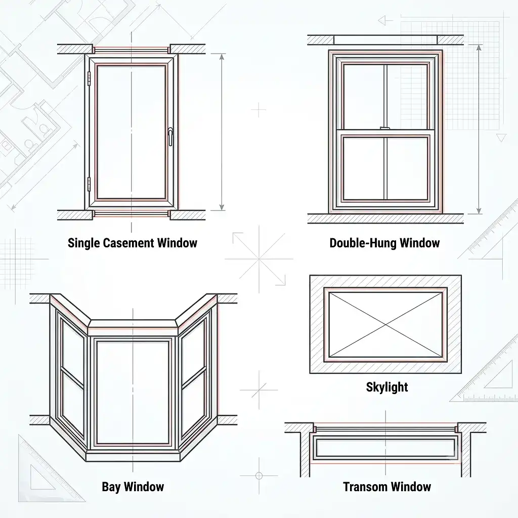
Key window symbol variations:
- Single casement window: Three lines in the wall, sometimes with a hinge indicator
- Double-hung window: Three lines with a center divider
- Bay window: An angled projection from the wall with glass lines along the face
- Skylight: A rectangle with diagonal cross lines, usually shown in a ceiling plan
- Transom window: A narrow three-line group positioned high on a wall
Windows are shown at the floor plan level even though they sit above floor height – this is a convention to indicate their position along the wall.
4. Staircase and Elevation Symbols
Stairs are among the more complex symbols because they convey vertical movement across a horizontal drawing.
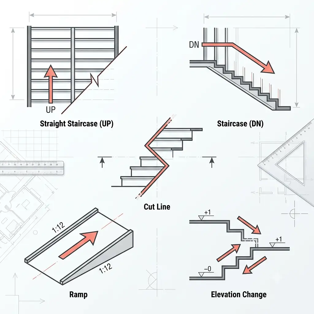
A standard staircase symbol includes:
- Parallel horizontal lines representing the individual steps (treads)
- An arrow pointing up (labeled “UP”) or down (labeled “DN”) showing the direction of travel
- A diagonal cut line (often shown as a zigzag) indicating where the view is cut off at the floor level
Reading tip: The arrow direction depends on the viewing floor. If you are reading the ground floor plan, the UP arrow points to the stairs going upward. If you are reading the second floor plan of the same staircase, the DN arrow applies.
Similarly, elevation changes and ramps are shown with directional arrows and slope ratios (such as 1:12 for ADA-compliant ramps).
5. Kitchen and Bathroom Fixture Symbols
Fixtures are drawn as simplified top-down (plan view) representations of the actual objects. These are among the most recognizable floor plan symbols because they closely resemble the real shapes.
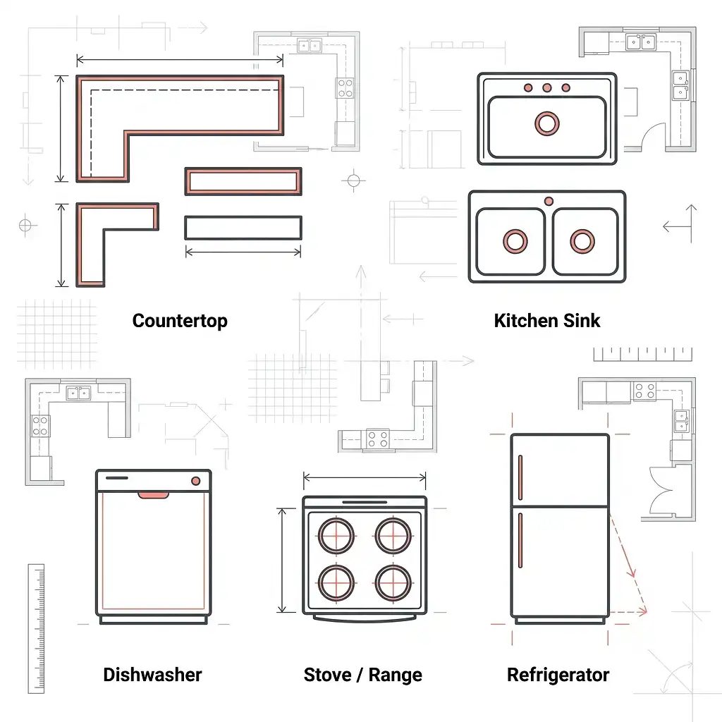
Kitchen symbols:
- Countertop: A rectangular outline along a wall
- Kitchen sink: A rectangle with one or two circles (basins) inside
- Dishwasher: A plain rectangle labeled “DW” or with a simple icon
- Stove/range: A rectangle with four small circles for burners
- Refrigerator: A rectangle, sometimes with a door swing arc shown
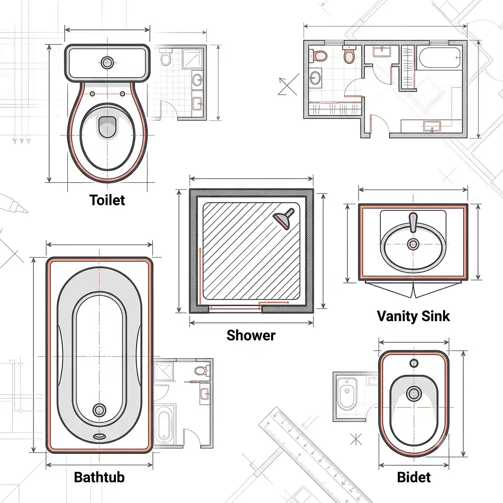
Bathroom symbols:
- Toilet: An oval (the tank) attached to a larger oval or rectangle (the bowl)
- Bathtub: A large rectangle with a smaller oval inside representing the tub basin
- Shower: A square with diagonal line hatching or a shower head icon
- Vanity/sink: A rectangle with a circle or oval for the basin
- Bidet: An elongated oval, similar in shape to a toilet but slightly smaller
Understanding these symbols is especially useful when evaluating plans for properties like hotels and multi-unit residential buildings – where fixture counts and layouts directly impact usability. If you need professionally drawn layouts, the team at The 2D3D Floor Plan Company produces detailed plans that clearly represent all fixture placements.
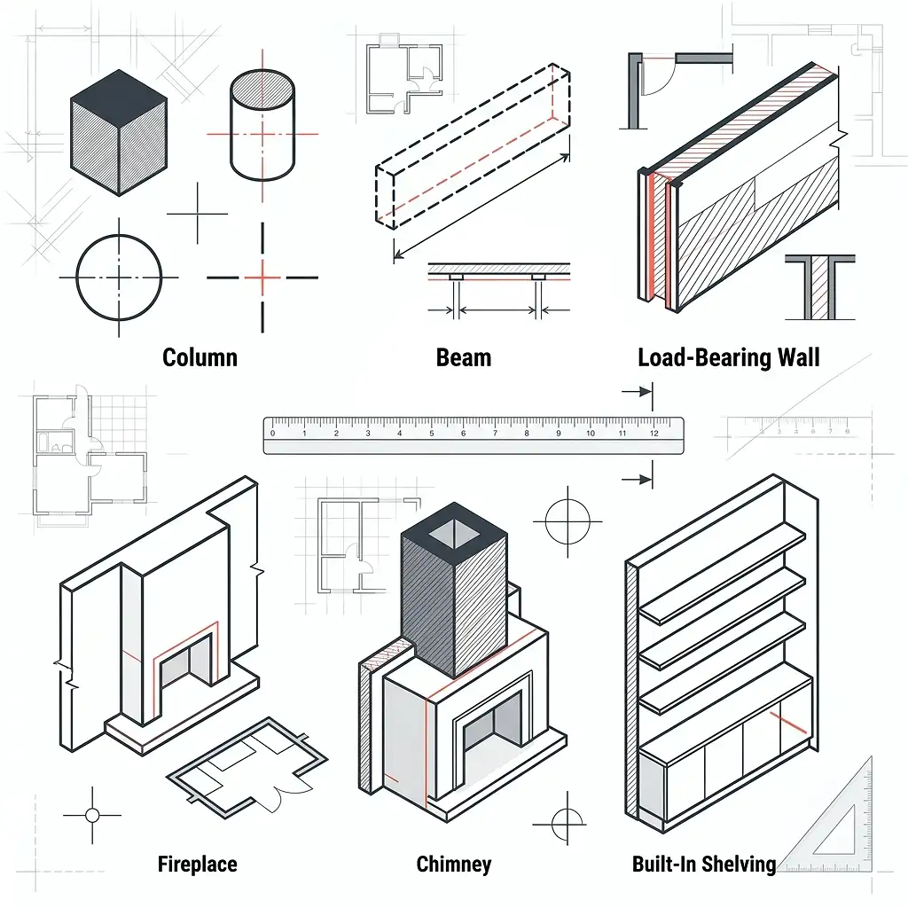
6. Structural and Architectural Symbols
Beyond furniture and fixtures, floor plans also contain symbols representing structural components:
Beyond furniture and fixtures, floor plans also contain symbols representing structural components:
- Columns: Solid filled squares or circles, sometimes with centerline cross markers
- Beams: Dashed rectangles showing span direction above the floor level
- Load-bearing walls: Indicated in the legend by a specific hatch pattern or heavier line weight
- Fireplace: A rectangle projecting slightly from a wall, often with a hearth outline
- Chimney: A solid or hatched square near a fireplace symbol
- Built-in shelving: A series of thin parallel lines in a fixed location
Line Types in Floor Plans: What They All Mean
Line types carry just as much meaning as the shapes themselves. Here is a reference for the most common ones:
| LINE TYPE | APPEARANCE | MEANING |
|---|---|---|
| Solid thick line | Continuous, heavy | Wall, major structure |
| Solid thin line | Continuous, light | Object outlines, fixtures |
| Dashed line | Short dashes | Hidden elements, overhead items |
| Dotted line | Dots only | Center lines, reference lines |
| Long dash – short dash | Alternating | Center axis lines |
| Zigzag or break line | Wavy or angled break | Drawing cut-off point |
| Dimension line | Thin with arrows | Measurements between points |
The dashed line is particularly important. When you see dashed lines above a room space, they usually represent something overhead – a beam, a skylight, a loft above, or upper cabinetry. This hidden-line convention is standard in architectural drawings worldwide.
How to Read Dimensions on a Floor Plan
Dimensions tell you the actual physical size of spaces and elements. They are typically shown as thin lines with small arrows or tick marks at each end, with the measurement written above or beside the line.
Most professional floor plans include:
- Overall building dimensions along the outside perimeter
- Room-to-room dimensions measuring between walls
- Opening dimensions for doors and windows (width x height, e.g., 3′-0″ x 6′-8″)
- Ceiling heights noted in text form within the room
For a deeper look at how dimensions are used in professional drawings, the resource on 2D floor plans with dimensions from The 2D3D Floor Plan Company walks through real-world examples in detail.
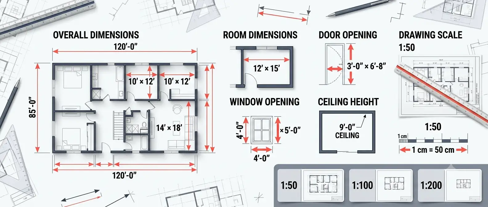
Scale note: Floor plans are always drawn to scale. A plan at 1:50 means every 1 cm on paper equals 50 cm in reality. Always check the stated scale before measuring anything on a printed floor plan.
Common Floor Plan Notations and Abbreviations
Beyond symbols, floor plans use standard abbreviations to label rooms, materials, and elements efficiently.
Room abbreviations:
- LR or LIV – Living Room
- DR – Dining Room
- KIT or K – Kitchen
- MBR or MBD – Master Bedroom
- BD or BR – Bedroom
- BA or BTH – Bathroom
- WIC – Walk-In Closet
- UTL – Utility Room
- GAR or G – Garage
Material and surface notations:
- CONC – Concrete
- CMU – Concrete Masonry Unit (block wall)
- GYP BD – Gypsum Board (drywall)
- INSUL – Insulation
- CLG – Ceiling
- FLR – Floor
Mechanical and electrical abbreviations:
- HVAC – Heating, Ventilation, and Air Conditioning
- EL or ELEC – Electrical panel
- GFI – Ground Fault Interrupter outlet (bathroom/kitchen)
- SD – Smoke Detector
- CO – Carbon Monoxide Detector
Electrical and Mechanical Symbols in Floor Plans
Full architectural sets often include a dedicated electrical plan layer. However, many residential floor plans show basic electrical symbols on the same drawing.
Common electrical symbols include:
- Single outlet: A circle with two short horizontal lines
- Duplex outlet: A circle with two horizontal lines (the standard wall plug)
- GFI outlet: Same as duplex but with “GFI” label
- Switch: An “S” with a small angled line
- Three-way switch: “S3” or “S” with a small superscript 3
- Ceiling light: A circle with a cross inside
- Recessed light: A circle with a dot in the center
- Ceiling fan: A circle with fan blade shapes extending outward
These symbols follow conventions established by the Institute of Electrical and Electronics Engineers (IEEE) and the American National Standards Institute (ANSI), which publishes standards for graphical symbols in technical drawings.
Floor Plan Symbol Differences: 2D vs. 3D Plans
Traditional 2D floor plans use the flat symbol conventions described throughout this guide. However, 3D floor plans represent the same information in a rendered, three-dimensional view – making symbols largely unnecessary because you can see the actual objects.
In a 3D floor plan:
- Walls are shown as physical structures with height and texture
- Doors and windows are visible as real openings
- Fixtures look like actual objects (a toilet looks like a toilet)
- Furniture is rendered with realistic proportions and material finishes
For buyers and renters unfamiliar with reading technical symbols, 3D plans dramatically reduce confusion. You can explore the full difference between the two formats in this comparison of 2D and 3D floor plans to understand which works best for your project.
Both formats have their place. Architects and contractors rely on 2D plans for precision. Marketing teams and sales presentations often favor 3D floor plans for their visual impact and immediate comprehension.
How Floor Plan Symbols Vary by Property Type
Not all floor plans use identical symbol sets. The symbols shift depending on the type of property and its purpose.
Residential Floor Plans
Standard residential plans include the symbols covered above – walls, doors, windows, kitchen and bathroom fixtures, stairs, and basic structural elements. The legend is usually compact.
Commercial and Office Floor Plans
Commercial plans include additional symbols for:
- Fire exits and emergency egress paths
- ADA-compliant elements (ramps, accessible restrooms)
- Electrical and data ports in detail
- HVAC duct paths and diffuser locations
- Modular workstation outlines
Hotel Floor Plans
Hotel plans add specialized symbols for:
- Room type codes (King, Double, Suite)
- Connecting door indicators
- Service corridor access points
- Housekeeping closets and linen drops
The planning complexity of large hospitality properties is significant. If you work in this sector, the detailed resource on hotel floor plans covers these specialized conventions in full.
Penthouse and Luxury Residential Plans
High-end residential plans sometimes include additional notations for smart home systems, custom millwork, and specialty structural features. See more detail on penthouse floor plan conventions for reference.
A Visual Guide to Reading a Floor Plan: Step-by-Step
Here is a practical process for reading any new floor plan clearly:
- Find the legend first. Before looking at the actual drawing, locate the legend or key. This tells you what all the symbols in this specific plan mean.
- Identify the scale. Note the stated scale ratio (1:50, 1:100, etc.) so you know the real-world dimensions.
- Trace the exterior walls. Identify the building’s outer boundary. This gives you the overall footprint.
- Locate entry points. Find the main entrance and all secondary doors to understand access and flow.
- Map the rooms. Read the room labels (or abbreviations) and trace how each space connects to the next.
- Check fixture placement. In kitchens and bathrooms, confirm where the major fixtures sit relative to the walls and each other.
- Note vertical elements. Find stairs, elevators, and any changes in floor level.
- Review the dimensions. Check key measurements – room lengths, door widths, hallway clearances.
- Look for dashed lines. Identify any hidden elements above: beams, loft levels, overhead cabinets.
- Cross-reference with other views. A floor plan works alongside elevations and sections for a complete picture. Understanding how site plans differ from floor plans also helps when reviewing full architectural document sets.
Common Mistakes When Reading Floor Plan Symbols
Even experienced reviewers make these errors. Avoiding them will save you time and prevent misunderstandings:
Ignoring the legend: Every floor plan can have slight symbol variations. Always read the legend before assuming you know what a symbol means.
Misreading door swings: Forgetting that a door arc represents required clearance leads to poor furniture placement – and blocked doors.
Confusing solid and dashed lines: A dashed rectangle above a kitchen island is not a structural wall; it typically indicates upper cabinetry. Treating it as a wall changes your whole interpretation.
Skipping the scale: Estimating room size without checking scale results in significant errors. A room can look large on paper but be barely functional in real life if the scale is 1:100.
Overlooking North arrows: Floor plans include a compass rose or North indicator. Ignoring it means you may misjudge the sun orientation and natural light quality of rooms.
Assuming standard symbol use: Symbols can vary between countries, software platforms, and architectural firms. When in doubt, ask for clarification or check the legend.
Expert Tips for Getting More From Floor Plans
Here are practical insights from professionals who work with floor plans every day:
- Print at stated scale when possible. A scaled print lets you physically measure rooms with a ruler rather than relying on the drawn dimensions.
- Trace traffic flow. Use a pencil to trace the natural paths you would walk from the entrance to each room. Bottlenecks become obvious.
- Count door swings against furniture. Sketch in major furniture pieces (to scale) and check how many doors you are blocking.
- Check the stair footprint. Stairs consume more floor area than most people expect. Confirm both the footprint at the lower level and the opening at the upper level.
- Verify window placement against sun direction. Using the North arrow, identify which rooms get morning versus afternoon light.
- Use 3D conversions for client presentations. If you need to share plans with clients or stakeholders who are not comfortable reading 2D drawings, converting to a 3D view removes all symbol ambiguity. The floor plan to 3D conversion service is designed specifically for this purpose.
Frequently Asked Questions About Floor Plan Symbols and Legends
Q: What is the difference between a floor plan symbol and a floor plan legend? A: A floor plan symbol is an individual graphic element used to represent a physical feature – such as a door, window, or fixture. The floor plan legend (or key) is the reference table that explains what each symbol in that specific plan means. Think of symbols as the words and the legend as the dictionary.
Q: Are floor plan symbols the same in every country? A: Not exactly. Most countries follow similar conventions based on ISO standards or local equivalents, but there are differences. For example, the representation of electrical outlets and some structural elements varies between North American, European, and Australian drawing conventions. Always check the legend provided with any floor plan you receive.
Q: What does a dashed line mean in a floor plan? A: A dashed line typically represents something that exists above the floor level being shown – such as a beam overhead, upper kitchen cabinets, a loft opening, or a change in ceiling height. It can also indicate a hidden structural element below the floor surface, depending on context. Always check the legend to confirm what dashed lines mean in a specific plan.
Q: How do I read window symbols on a floor plan? A: Windows appear as three parallel lines within a gap in the wall. The outer two lines represent the wall surfaces, and the thin middle line represents the glass pane. For specialty windows like bay windows or skylights, additional lines indicate the projection or overhead position.
Q: What is the purpose of a North arrow on a floor plan? A: The North arrow indicates the compass orientation of the building as drawn. It allows you to determine which rooms face which direction – useful for understanding natural light, prevailing wind, and street-facing facades.
Q: Can floor plan symbols and legend keys vary between software programs? A: Yes. Different floor plan software tools use slightly different default symbol libraries. CAD-based programs often follow ANSI or ISO standards closely, while consumer-grade design apps may use simplified or stylized symbols. Professional plans produced by architectural firms or specialist services like The 2D3D Floor Plan Company follow recognized industry standards to ensure clarity.
Q: What does the arc on a door symbol represent? A: The arc shows the swing path of the door as it opens. This indicates the clearance zone – the floor area that must remain unobstructed so the door can operate freely. Interior designers and furniture planners use this information to avoid placing sofas, tables, or other objects in the door’s path.
Q: How are stairs shown on a floor plan? A: Stairs are drawn as a series of horizontal parallel lines (the treads), with an arrow showing the direction of travel (UP or DN) and a diagonal cut line showing where the drawing is truncated at floor level.
Conclusion
Floor plan symbols and legend markings are the universal language of architectural drawing. Once you understand that walls are parallel lines, doors carry arcs, dashed lines indicate hidden elements, and fixtures look like simplified versions of themselves, you can read virtually any floor plan with confidence.
The key habits are simple: always read the legend first, check the scale, trace the flow, and verify door swings before placing any furniture. Whether you are reviewing a single-family home plan or a large commercial development, these principles apply equally.
If you are ready to work with professionally drawn floor plans – or want to convert existing sketches, photos, or rough drawings into clean, accurate 2D or 3D plans – explore the full range of services at The 2D3D Floor Plan Company. From 2D colored floor plans to fully rendered 3D exterior visuals, every deliverable is built on the same precise symbolic language this guide has explained.